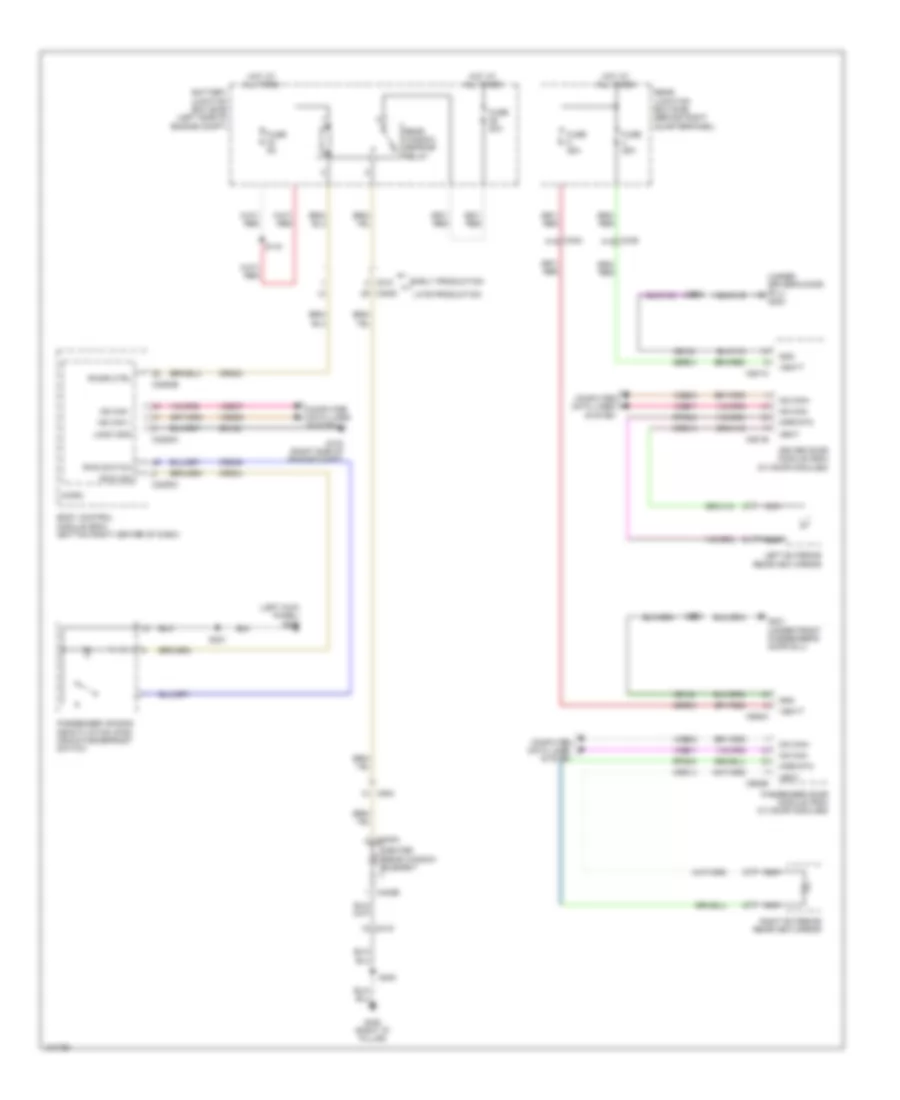
DEFOGGERS
Defoggers Wiring Diagram for Ford Escape SE 2014
List of elements for Defoggers Wiring Diagram for Ford Escape SE 2014:
- (left kick panel) g205
- (under driver's door sill) g203
- Battery junction box (bjb) (left side of engine compt)
- Body control module (bcm) (bottom right center of dash)
- C210
- C2280a
- C2280b
- C2280c
- C3053
- C339 a14
- C340 a14
- C402a
- C402b
- C410
- C501a
- C501b
- C652a
- C652b
- C934
- Computer data lines system
- Crd02
- Crd04
- Crd09
- Crd13
- Crd14
- Driver door module (ddm) (w/ door modules)
- Early production
- Fuse 20a
- Fuse 25a
- Fuse 5a
- G103 (right side of engine compt)
- G201 (under front passenger's door sill)
- G400 (right "d" pillar)
- Gd123
- Gd134
- Gd140
- Gnd
- Heat
- Heated rear window element
- Hot at all times
- Late production
- Left exterior rearview mirror
- Logic gnd
- Micro
- Mirr rtn
- Ms can +
- Ms can -
- Ms can+
- Ms can-
- Nca
- Passenger air bag deactivation (pad) indicator/defrost switch
- Passenger door module (pdm) (w/ door modules)
- Rear junction box (rjb) (behind right quarterpanel)
- Rear window defrost relay
- Right exterior rearview mirror
- Rpm05
- Rpm08
- Rwd ind
- Rwd switch
- Rwdr ctrl
- S144
- S221
- S400
- S500
- S600
- Sbr04
- Sbr05
- Vbatt
- Vdb06
- Vdb07
- Vdbo6
- Vdbo7
 English