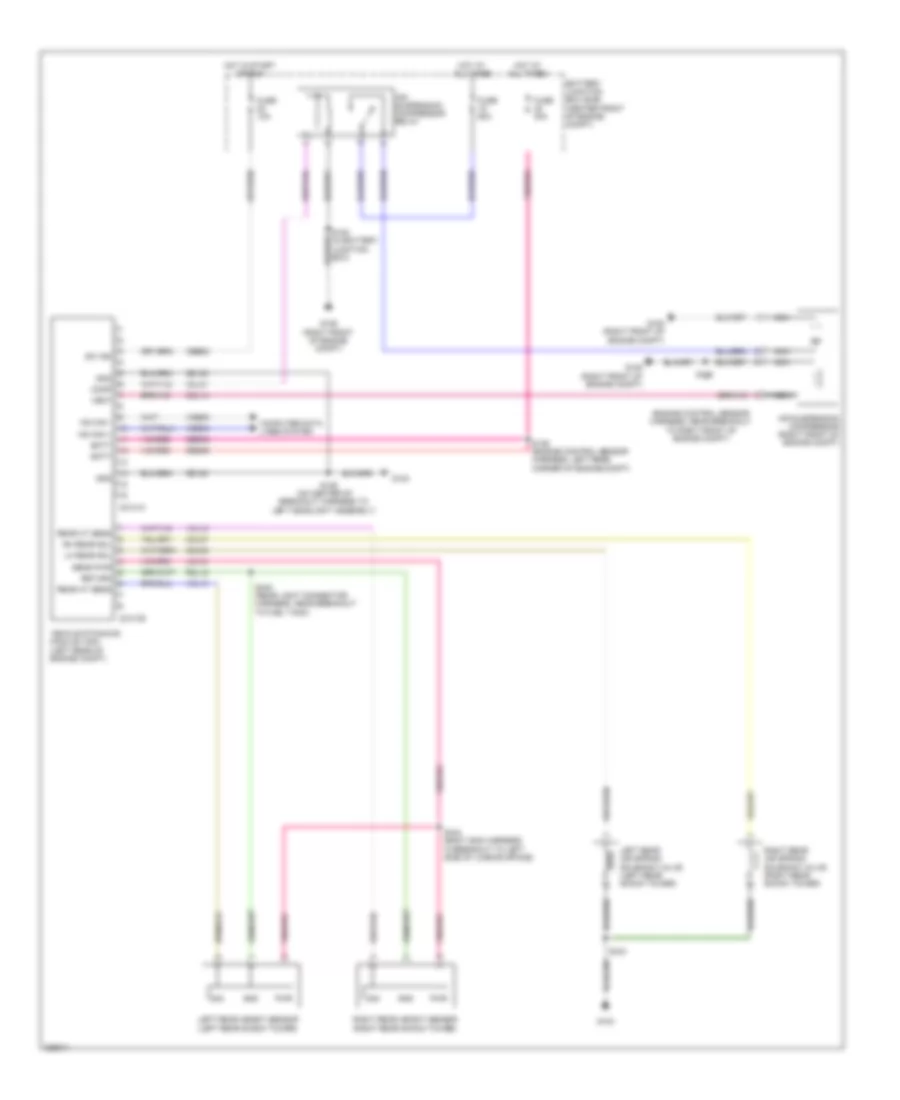
ELECTRONIC SUSPENSION
Electronic Suspension Wiring Diagram for Ford Expedition 2010
List of elements for Electronic Suspension Wiring Diagram for Ford Expedition 2010:
- (engine control sensor harness, near breakout to right front of engine compt)
- (on center of breakout harness to left headlight assembly)
- Air suspension compressor (right front of engine compt)
- Air suspension compressor relay
- Batt
- Battery junction box (bjb) (center front of engine compt)
- C2131a
- C2131b
- Cbb53
- Ccl01
- Ccl05
- Ccl07
- Ccl14
- Comp
- Computer data lines system
- Fuse 10a
- Fuse 30a
- Fuse 60a
- G103
- G105 (right front of engine compt)
- G106 (right front of engine compt)
- Gd120
- Gnd
- Hot at all times
- Hot in start or run
- Hs can +
- Hs can -
- Lcl12
- Left rear air spring solenoid valve (left rear shock tower)
- Left rear height sensor (left rear shock tower)
- Lh rear sol
- Nca
- Pwr
- Rcl12
- Rear ht sens
- Return
- Rh rear sol
- Right rear air spring solenoid valve (right rear shock tower)
- Right rear height sensor (right rear shock tower)
- S108
- S122 (in battery junction box)
- S129
- S136 (engine control sensor harness, left rear corner of engine compt)
- S443
- S444 (body main harness, in breakout to left side of loading space)
- S445 (rear light connector harness, near breakout to fuel tank)
- Sbb48
- Sens pwr
- Sig
- Sw ign
- Vcl12
- Vcl13
- Vdb04
- Vdb05
- Vehicle dynamics module (vdm) (left rear of engine compt)
- Vent
 English