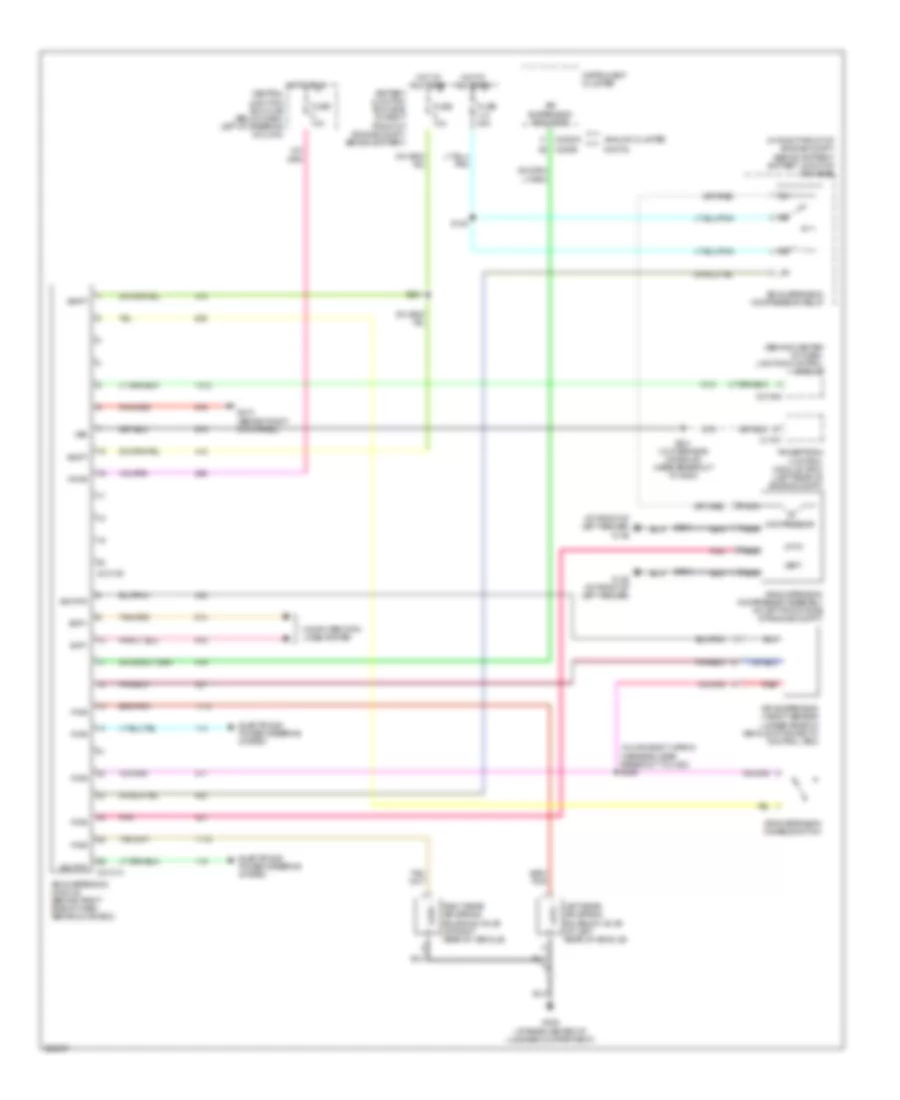
ELECTRONIC SUSPENSION
Electronic Suspension Wiring Diagram for Mercury Grand Marquis LS 2005
List of elements for Electronic Suspension Wiring Diagram for Mercury Grand Marquis LS 2005:
- (at front of left fender) g105
- (behind center of dash) lighting control module
- (in main body wiring harness, near breakout to c423) s450
- (in right front of engine compt, behind battery) battery junction box (bjb)
- Air suspension compressor assembly (at left front side of engine compt)
- Air suspension compressor relay
- Air suspension disable switch
- Air suspension height sensor (under rear of vehicle attached to control arm)
- Air suspension indicator
- Air suspension module (behind right side of dash, above glove box)
- Analog cluster
- Battery junction box (bjb) (in right front of engine compt, behind battery)
- C175t
- C2131a
- C2131b
- C2145a
- C220b
- C2220a
- Central junction box (cjb) (below dash, left of steering column)
- Compressor
- Computer data lines system
- Digital
- Electronic power steering system
- Fuse 10a
- Fuse 30a
- G102 (at front of left fender)
- G210 (behind right kick panel)
- G405 (at rear center of luggage compartment)
- Hot at all times
- Hot in run
- Instrument cluster
- Left rear air spring solenoid valve (at left rear of vehicle)
- Nca
- Pnk
- Powertrain control module (pcm) (left rear of engine compt)
- Pwr
- Red
- Right rear air spring solenoid valve (at right rear of vehicle)
- S112
- S113
- S120
- S221
- S231 (w/ overhead console) (near breakout to g200)
- Scp+
- Scp-
- Sig rtn
- Vbatt
- Vent
- Vpwr
- Vss
 English