СИСТЕМА ПЕРЕДАЧИ ДАННЫХ
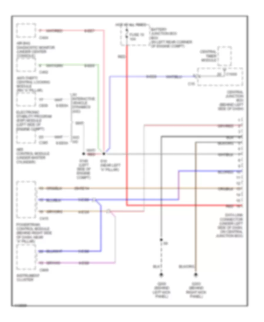
Электросхема компьютерной линии передачи данных CAN, С Регулирование тягового усилия для Ford Focus SE 2001
 https://portal-diagnostov.com/license.html
Automotive Electricians Portal FZCO
Automotive Electricians Portal FZCO
https://portal-diagnostov.com/license.html
https://portal-diagnostov.com/license.html
Automotive Electricians Portal FZCO
Automotive Electricians Portal FZCO
Электросхема компьютерной линии передачи данных CAN, С Регулирование тягового усилия для Ford Focus SE 2001 - Список элементов:
- (dash harn, behind left side of dash) s17
- (left side of engine compt) s140
- 29-re14
- 4-eg6
- 4-eg8
- 4-eg9
- 5-eg6
- 5-eg8
- 5-eg9
- 8-ee6a
- 8-ee7
- 8-ee8
- 8-ee9
- Abs control module (under master cylinder)
- Air bag diagnostic monitor (under center console)
- Anti-theft/ central locking module (rh "a" pillar)
- Battery junction box box (in left rear corner of engine compt)
- C1000
- C15
- C385
- C415
- C424
- C452
- C809
- C818
- C830
- Central junction box (behind left side of dash)
- Central timer module
- Data link connector (under left side of dash, on central junction box)
- Electronic stability program (esp) module (left side of engine compt)
- Fuse 10 10a
- G200 (behind left kick panel)
- G203 (behind right kick panel)
- Hot at all times
- Instrument cluster
- Powertrain control module (behind right side of dash, near "a" pillar)
- Red
- S10 (near left "a" pillar)
- S16 (dash harn, behind left side of dash)
- Steering position sensor (on steering column)
- W/ interactive vehicle dynamics (ivd)
- W/o ivd
Электросхема компьютерной линии передачи данных CAN, без Регулирование тягового усилия для Ford Focus SE 2001
Электросхема компьютерной линии передачи данных CAN, без Регулирование тягового усилия для Ford Focus SE 2001 - Список элементов:
- 29-re14
- 4-eg8
- 4-eg9
- 5-eg8
- 5-eg9
- 8-ee6a
- 8-ee7
- 8-ee8
- 8-ee9
- Abs control module (under master cylinder)
- Air bag diagnostic monitor (under center console)
- Anti-theft/ central locking module (rh "a" pillar)
- Battery junction box box (in left rear corner of engine compt)
- C1000
- C15
- C385
- C415
- C424
- C452
- C809
- C830
- Central junction box (behind left side of dash)
- Central timer module
- Data link connector (under left side of dash, on central junction box)
- Electronic stability program (esp) module (left side of engine compt)
- Fuse 10 10a
- G200 (behind left kick panel)
- G203 (behind right kick panel)
- Hot at all times
- Instrument cluster
- Powertrain control module (behind right side of dash, near "a" pillar)
- Red
- S10 (near left "a" pillar)
- S140 (left side of engine compt)
- W/ interactive vehicle dynamics (ivd)
- W/o ivd

 Čeština
 Dansk
Dansk Deutsch
 Ελληνικά
 English
 Español
 Suomi
Suomi Français
 Français
 עברית
עברית Hrvatski
 Magyar
 Italiano
 日本語
日本語 한국어
한국어 Nederlands
 Polski
 Português
 Português
 Română
 Русский
 Slovenčina
 Slovenščina
 Svenska
 Türkçe
 中文 (中国)