ENGINE PERFORMANCE
5.4L
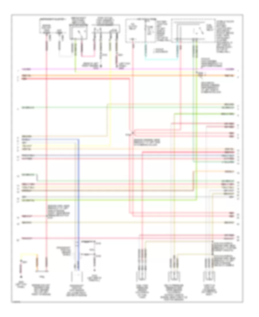
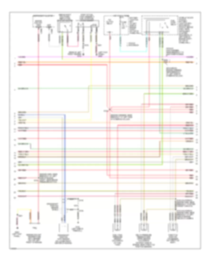
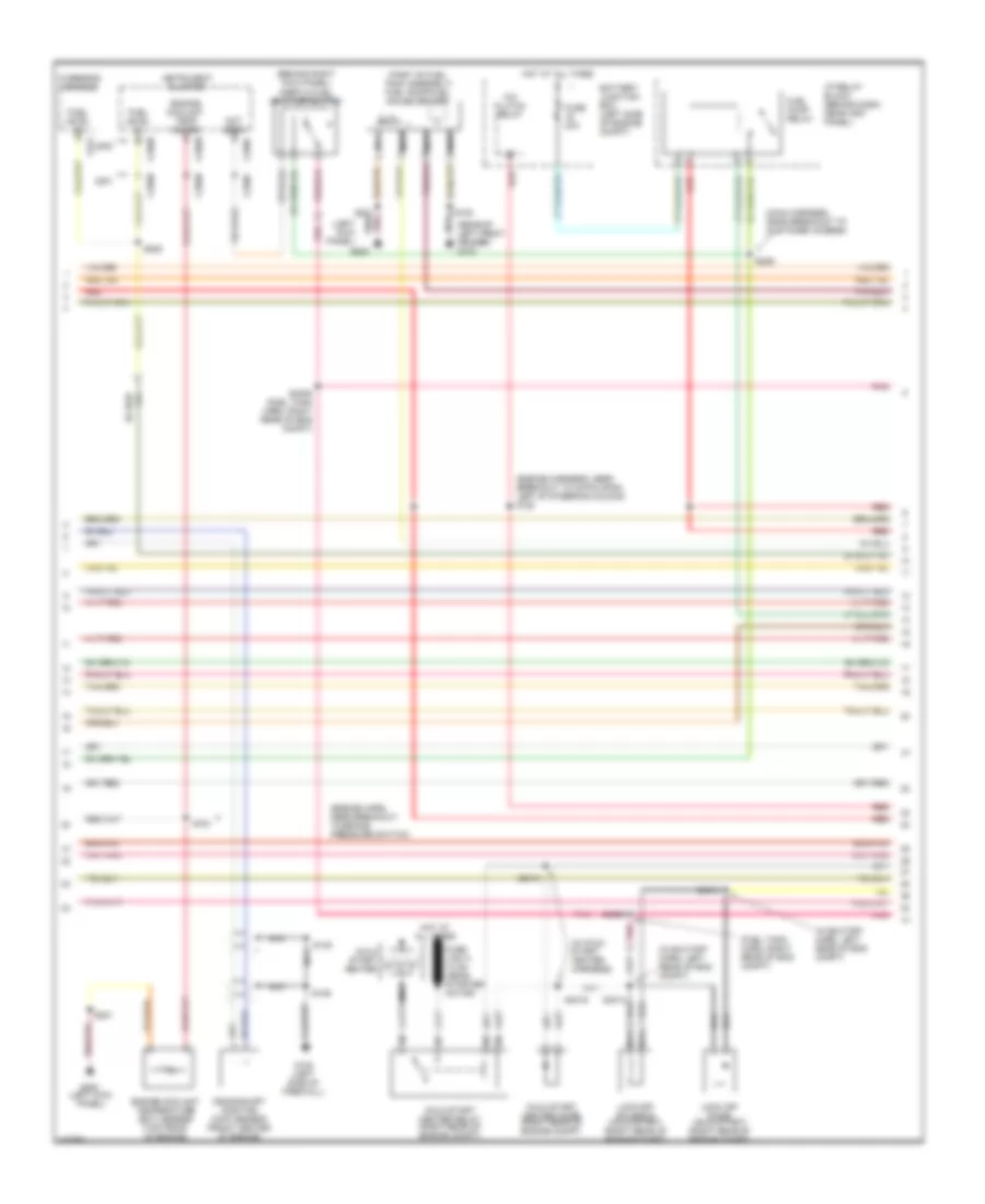
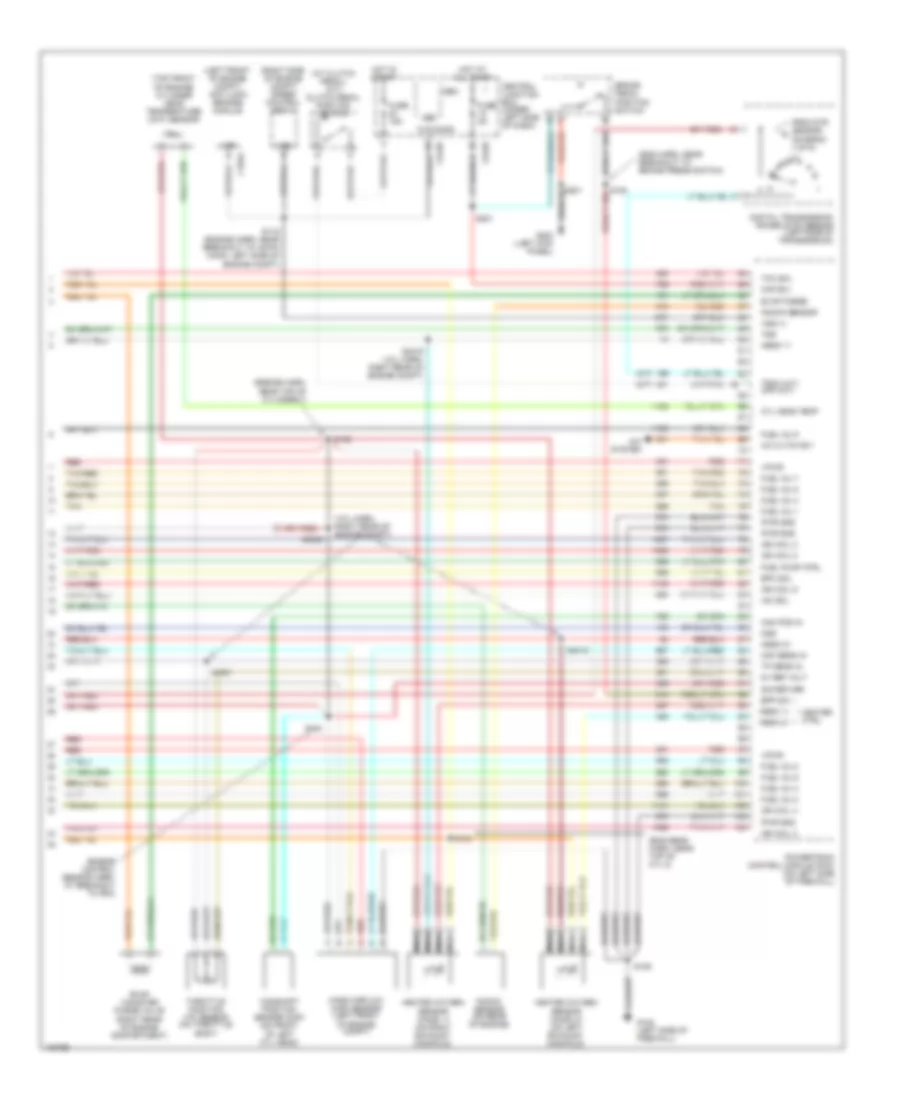
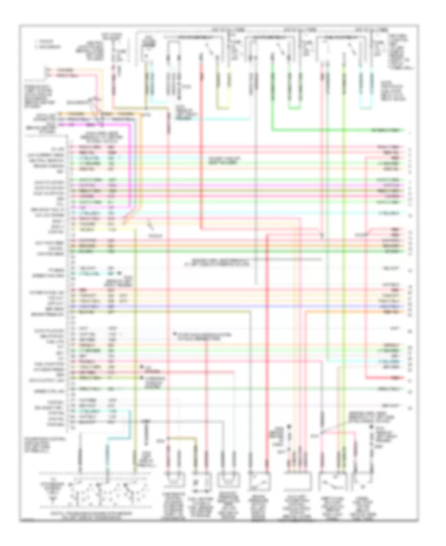
5.4L, Engine Performance Wiring Diagram (1 of 4) for Ford Cab & Chassis F350 Super Duty 2001

List of elements for 5.4L, Engine Performance Wiring Diagram (1 of 4) for Ford Cab & Chassis F350 Super Duty 2001:
- (engine harn, near breakout at left side of engine compt)
- (engine sensor harn, near breakout at right side of engine, above cylinder 3)
- (left kick panel)
- (main harn, near breakout at center of dash, on dlc)
- (not used)
- (pickup)
- (rear of left front fender)
- 4x4 high/low indicator switch
- 4x4 low ind sw
- 4x4 low ind
- A/c press sw
- A/c system
- Anti-theft system
- Battery junction box (in left side of engine compt, on top of wheelwell)
- C242b
- C250b
- C250c
- Ccs
- Central junction box (behind lower left side of dash)
- Ckp(+)
- Ckp(-)
- Coil on plug
- Cust access
- Customer access
- Data link (+)
- Data link (-)
- Data link connector (dlc) (behind center of dash)
- Data output
- Diag grd
- Digital transmission range (dtr) sensor (on left side of transmission)
- Egr sol
- Fuel gauge
- Fuel gauge in
- Fuel pump mon
- Fuse 10a
- Fuse 20a
- Fuse 30a
- G102 (left side of firewall)
- G104
- G200
- Hego 12
- Hot at all times
- Hot in run or start
- Iat
- Ign coil 1
- Ign coil 3
- Ign coil 5
- Ign coil 6
- Instrument cluster
- Knock sensor
- Maf
- Mil ind
- Nca
- Not used
- O/d off ind
- Overdrive cancel switch (a/t)
- Overhead console
- Pcm power diode
- Pcm power relay
- Pickup excursion
- Powertrain control module (pcm) (on left side of firewall)
- Pwr gnd
- R n
- Radio noise capacitor (on left side of engine)
- Radio noise capacitor (on right side of engine)
- Red
- Reprog pwr
- S102
- S105
- S106
- S129 (calif)
- S130 (engine harn, near breakout at throttle body)
- S135
- S179
- S201
- S208
- S213 s271
- S284
- S286
- Shift sol 1
- Shift sol 2
- Tach
- Tcs
- Temp output
- Tft
- To dtr sensor (diagram 4 of 4)
- Tr1
- Tr2
- Tr4
- Trans ctrl ind
- Transmission control switch
- Vss (-)
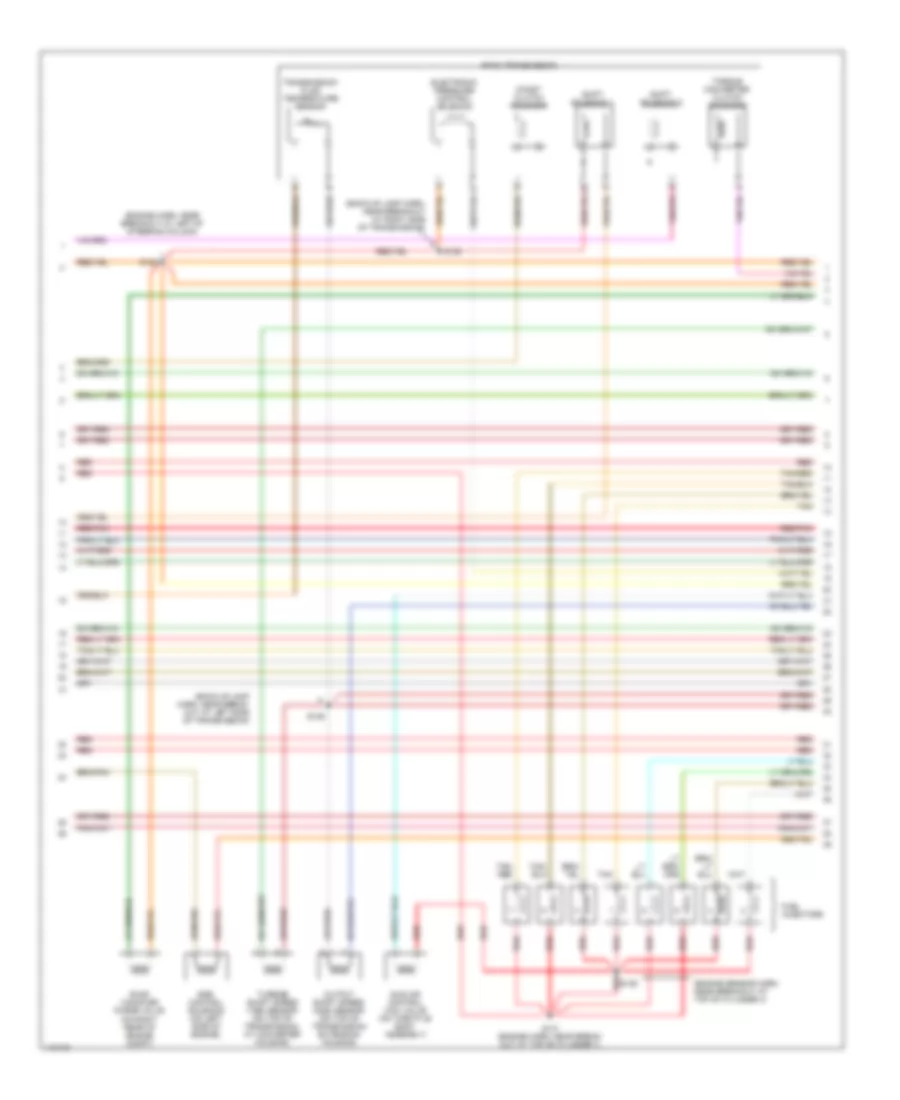
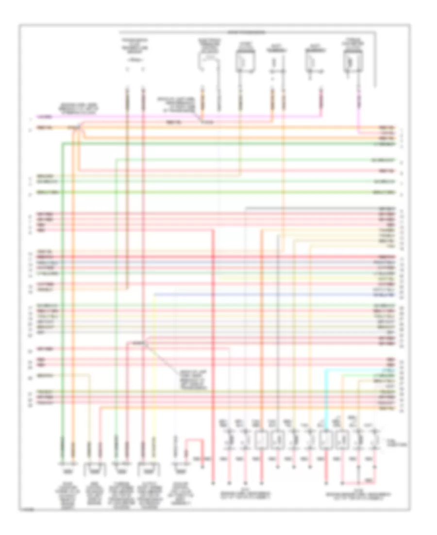
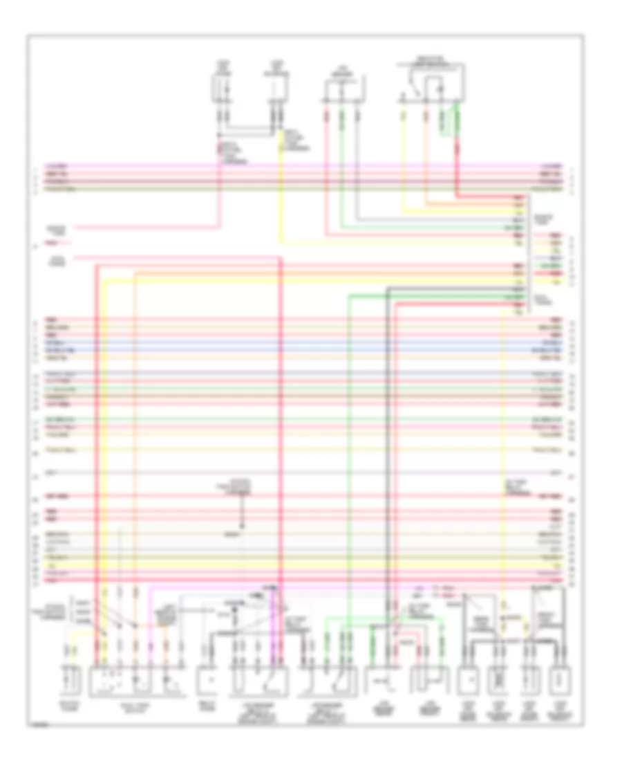
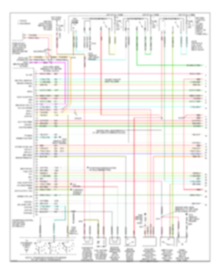
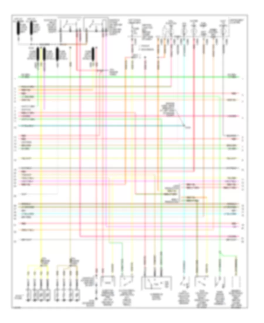
5.4L, Engine Performance Wiring Diagram (2 of 4) for Ford Cab & Chassis F350 Super Duty 2001
List of elements for 5.4L, Engine Performance Wiring Diagram (2 of 4) for Ford Cab & Chassis F350 Super Duty 2001:
- (behind right kick panel) inertia fuel shut-off switch
- (engine harn, near breakout at left side of engine compt, near brake pressure switch) s104
- (engine harness, near breakout at left side of steering column)
- (excursion: engine harness, near breakout at left side of steering column)
- (left kick panel) g200
- (not used)
- (part of fuel tank assembly) fuel pump/fuel gauge sender
- (pickup: main harness, near breakout to customer access)
- (rear of left front fender) g104
- A/c clutch relay
- Battery junction box (in left side of engine compt, on top of wheelwell)
- C250b
- C250c
- Crankshaft position (ckp) sensor (on lower front center of engine)
- Crankshaft position sensor shield
- Delta pressure feedback egr (dpfe) sensor (california) (on right side of engine, near throttle position sensor)
- Engine coolant temp gauge
- Engine coolant temperature (ect) sender (on top left front of engine)
- Fuel pump relay
- Fuel tank pressure sensor (california) (at fuel tank)
- Fuse 20a
- G102 (left side of firewall)
- G200 (left kick panel)
- Hot at all times
- I/p relay block (pickup) battery junction box (excursion) (pickup: behind dash, near instrument cluster) (excursion: in left side of engine compt, on top of wheelwell)
- Instrument cluster
- Nca
- Pickup excursion
- Red
- Red/pnk
- S102
- S106
- S123
- S128 (california) (engine harn, near breakout to after- market circuits)
- S133 (california) (engine harn, near breakout at left side of engine, above cylinder 6)
- S145
- S201
- S226 s164
- Throttle position (tp) sensor (on throttle body)
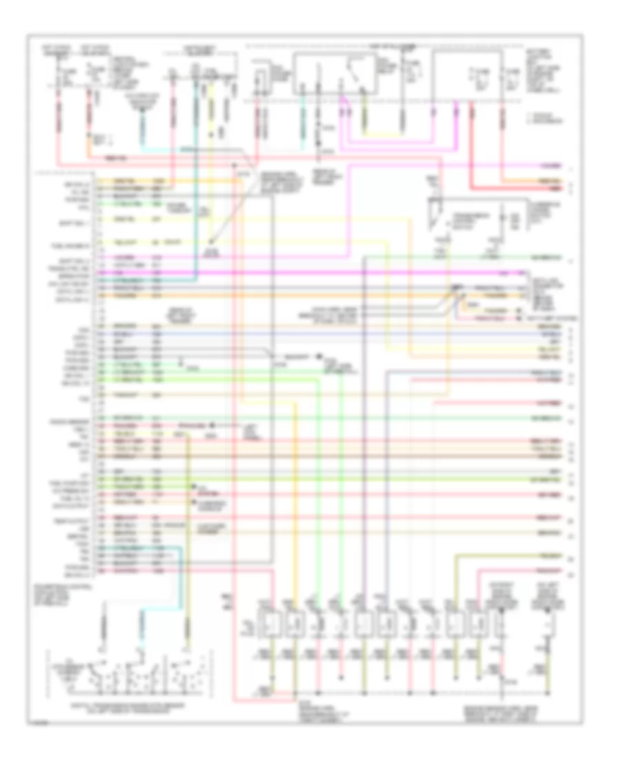
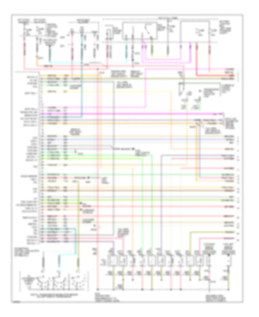
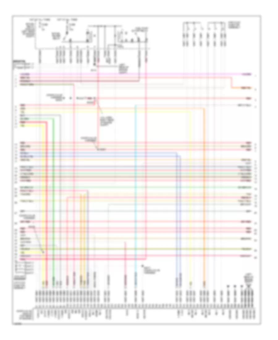
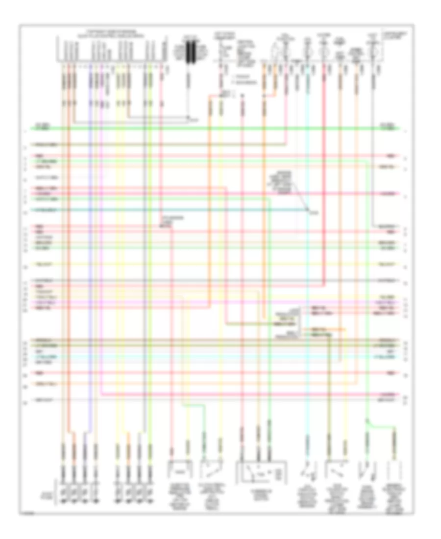
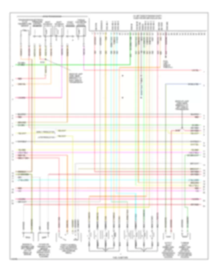
5.4L, Engine Performance Wiring Diagram (3 of 4) for Ford Cab & Chassis F350 Super Duty 2001
List of elements for 5.4L, Engine Performance Wiring Diagram (3 of 4) for Ford Cab & Chassis F350 Super Duty 2001:
- (back-up lamp harn, near break- out at left side of transmission)
- (back-up lamp harn, near breakout at right side of transmission)
- (engine harn, near breakout at left of steering column)
- (engine sensor harn, near breakout at top of cylinder 3)
- (on right rear of engine compt)
- 4r100 transmission
- Coast clutch solenoid
- Egr control solenoid (on left side of engine)
- Electronic pressure control solenoid
- Evap canister purge valve
- Fuel injectors
- Idle air control (iac) valve (on throttle body assembly)
- Output shaft speed (oss) sensor (on top of transmission extension housing)
- Red
- Red/pnk
- S122
- S131 (engine harn, near break- out at top of cylinder 7)
- S136
- S138
- S139
- Shift solenoid 1
- Shift solenoid 2
- Tan
- Tan/ red
- Tan/red
- Torque converter clutch solenoid
- Transmission fluid temperature sensor
- Turbine shaft speed (tss) sensor (on top of transmission, at converter housing)
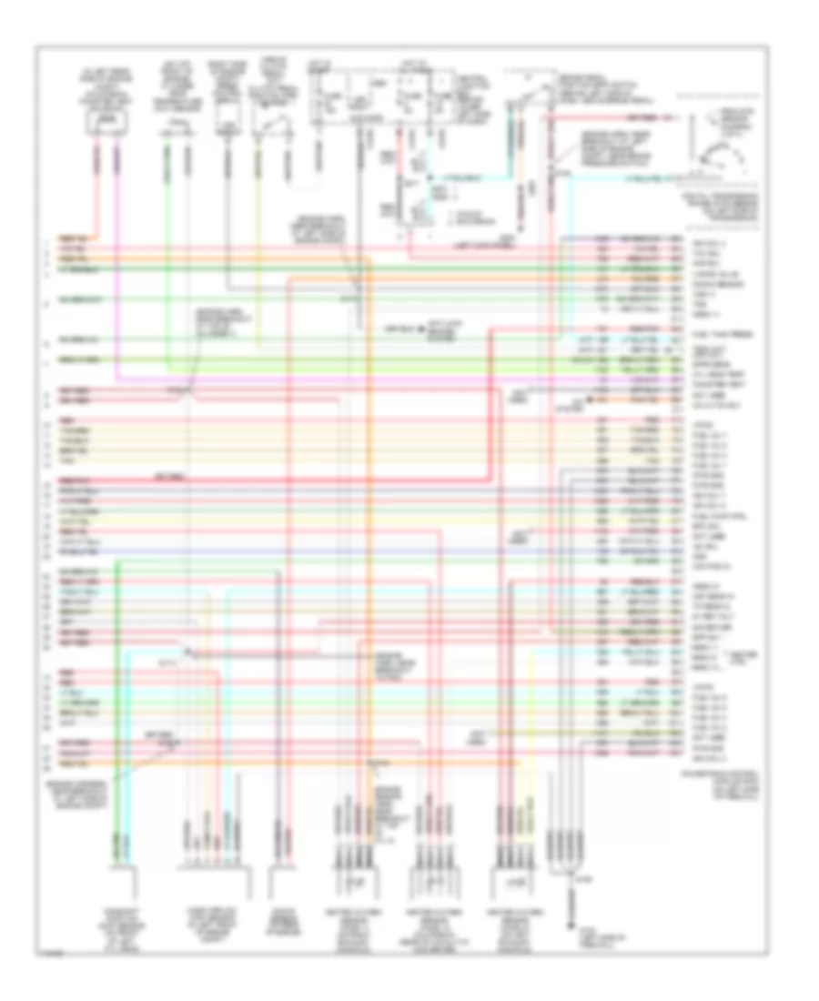
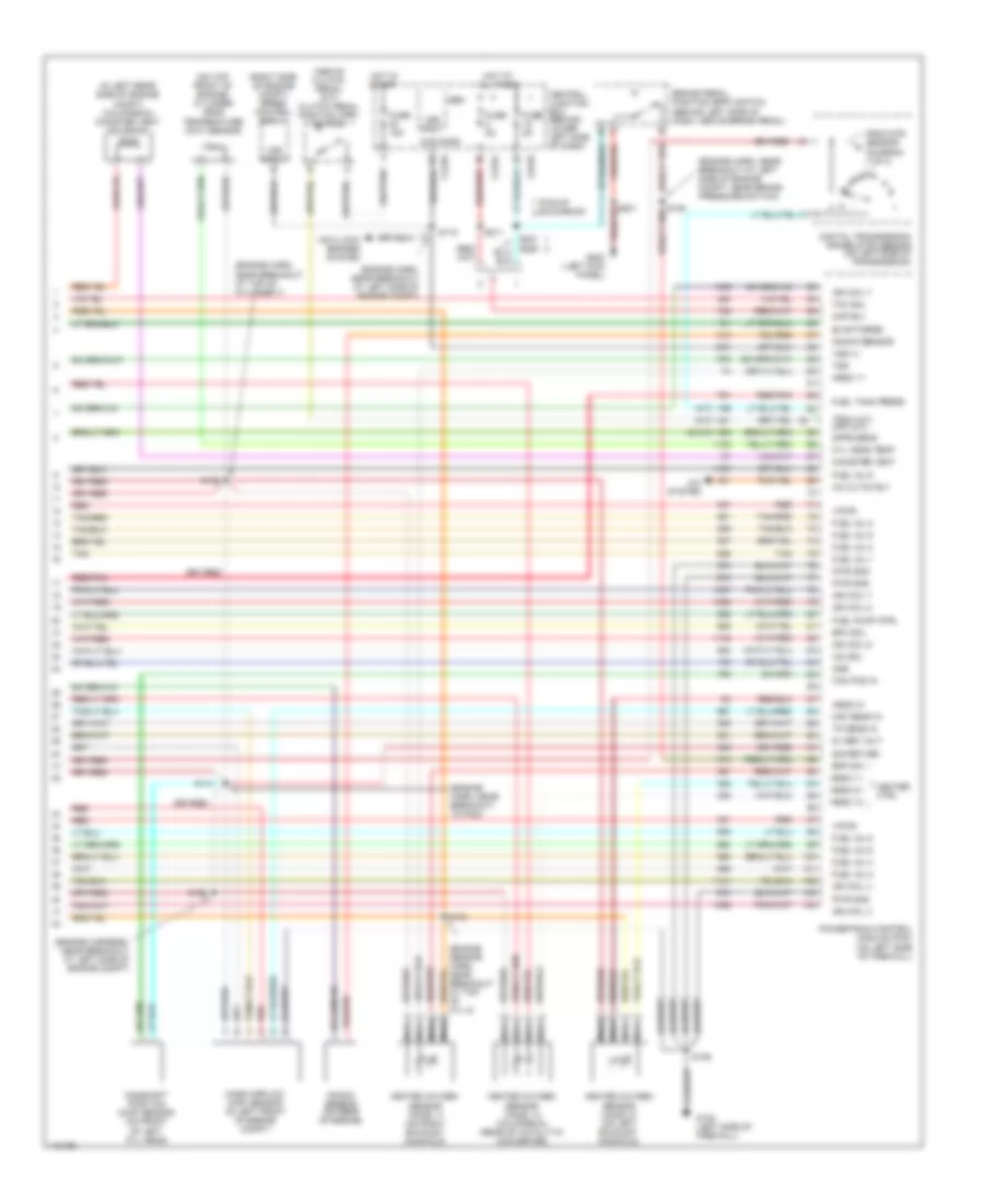
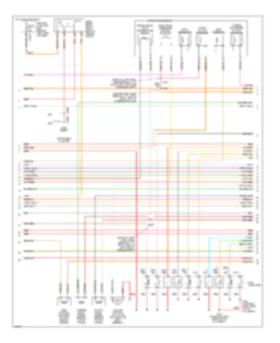
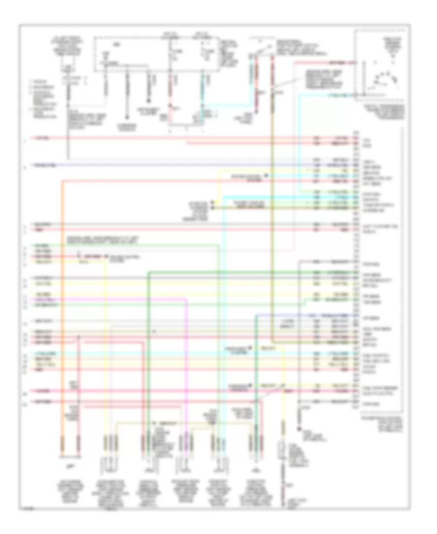
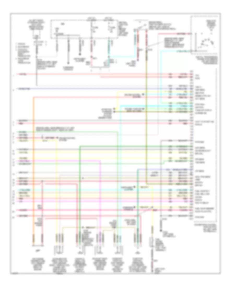
5.4L, Engine Performance Wiring Diagram (4 of 4) for Ford Cab & Chassis F350 Super Duty 2001
List of elements for 5.4L, Engine Performance Wiring Diagram (4 of 4) for Ford Cab & Chassis F350 Super Duty 2001:
- (a/t)
- (above clutch pedal) (m/t) clutch pedal position (cpp) switch
- (calif)
- (engine harn, near breakout at left side of engine compt)
- (engine harn, near breakout at left side of engine compt, near brake pressure switch)
- (engine harn, near breakout at top of cylinder 7)
- (engine harn, near breakout to pcm)
- (engine harness, near breakout at left side of engine compt)
- (in left rear side of engine compt) (california) canister vent solenoid
- (m/t)
- (not used)
- (on top front of engine) cylinder head temperature (cht) sensor
- (right side of engine compt) speed control servo
- 5v ref volt
- A/c cltch rly
- A/c system
- Anti-lock brakes system
- Bpp sw
- Brake pedal position (bpp) switch (behind left side of dash, above brake pedal)
- C240d
- C242a
- C242b
- Cam pos in
- Camshaft position (cmp) sensor (on front of left cyl head)
- Canister vent
- Central junction box (behind lower left side of dash)
- Cyl 8)
- Cyl head temp
- Digital transmission range (dtr) sensor (on left side of transmission)
- Dpfe sens
- Epc sol
- From dtr sensor (diagram 1 of 4)
- Fuel inj 1
- Fuel inj 2
- Fuel inj 3
- Fuel inj 4
- Fuel inj 5
- Fuel inj 6
- Fuel inj 7
- Fuel inj 8
- Fuel pump ctrl
- Fuel tank press
- Fuse 15a
- Fuse 5a
- G102 (left side of firewall)
- G200 (left kick panel)
- Gem
- Heated oxygen sensor (ho2s) 11 (on right exhaust manifold)
- Heated oxygen sensor (ho2s) 12 (california) (rear of catalytic converter)
- Heated oxygen sensor (ho2s) 21 (on left exhaust manifold)
- Heater ctrl
- Hego 11
- Hego 12
- Hego 21
- Hot at all times
- Hot in start
- Iac sol
- Ign coil 2
- Ign coil 4
- Ign coil 7
- Ign coil 8
- Kap b(+)
- Knock sensor
- Knock sensor (on rear of engine)
- Maf sens in
- Mass airflow (maf) sensor (in left front of engine compt)
- Nca
- Not used
- Oss
- Pickup excursion
- Powertrain control module (pcm) (on left side of firewall)
- Pwr gnd
- Red
- Red/pnk
- S106
- S114
- S115
- S129
- S132
- S134
- S211
- S221
- S288
- Sig return
- Tan
- Tan/red
- Tcc sol
- Tp sens in
- Tr3a (a/t) cpp (m/t)
- Tss
- Vapor valve
- Vpwr
- Vss (+)
- Vss input
6.8L
6.8L, Engine Performance Wiring Diagram (1 of 4) for Ford Cab & Chassis F350 Super Duty 2001
List of elements for 6.8L, Engine Performance Wiring Diagram (1 of 4) for Ford Cab & Chassis F350 Super Duty 2001:
- (calif)
- (engine harn, near breakout at left side of engine compt)
- (engine sensor harn, near breakout at right side of engine, above cylinder 3)
- (left kick panel)
- (main harn, near breakout at center of dash, on dlc)
- (on left side of engine) radio noise capacitor 2
- (on right side of engine) radio noise capacitor 1
- (pickup)
- (rear of left front fender)
- 4x4 high/low indicator switch
- 4x4 low ind sw
- 4x4 low ind
- A/c press sw
- A/c system
- Anti-theft system
- Battery junction box (in left side of engine compt, on top of wheelwell)
- C242b
- C250b
- C250c
- Case gnd
- Ccs
- Central junction box (behind lower left side of dash)
- Ckp(+)
- Ckp(-)
- Coil on plug
- Customer access
- Data link (+)
- Data link (-)
- Data link connector (dlc) (behind center of dash)
- Data output
- Digital transmission range (dtr) sensor (on left side of transmission)
- Egr sol
- Eprom pwr
- Fuel gauge
- Fuel gauge in
- Fuel inj 10
- Fuel pump mon
- Fuse 10a
- Fuse 20a
- Fuse 30a
- G102 (left side of firewall)
- G104
- G200
- Hego 12
- Hot at all times
- Hot in run or start
- Iat
- Ign coil 1
- Ign coil 10
- Ign coil 5
- Ign coil 6
- Instrument cluster
- Knock sensor
- Maf
- Mil ind
- Nca
- O/d off ind
- Overdrive cancel switch (a/t)
- Overhead console
- Pcm power diode
- Pcm power relay
- Pickup excursion
- Power take-off
- Powertrain control module (pcm) (on left side of firewall)
- Pto
- Pwr gnd
- R n
- Red
- S102
- S105
- S106
- S129 (calif)
- S130 (engine harn, near breakout at throttle body)
- S135
- S179
- S201
- S208
- S213 s271
- S284
- S286
- Shift sol 1
- Shift sol 2
- Tach
- Tcs
- Temp output
- Tft
- To dtr sensor (diagram 4 of 4)
- Tr1
- Tr2
- Tr4
- Trans ctrl ind
- Transmission control switch
- Vss
- Vss (-)
6.8L, Engine Performance Wiring Diagram (2 of 4) for Ford Cab & Chassis F350 Super Duty 2001
List of elements for 6.8L, Engine Performance Wiring Diagram (2 of 4) for Ford Cab & Chassis F350 Super Duty 2001:
- (behind right kick panel) inertia fuel shut-off switch
- (engine harn, near breakout at left side of engine compt, near brake s104 pressure switch)
- (engine harness, near breakout at left side of steering column)
- (excursion: engine harness, near breakout at left side of steering column)
- (left kick panel) g200
- (not used)
- (part of fuel tank assembly) fuel pump/fuel gauge sender
- (pickup: main harness, near breakout to customer access)
- (rear of left front fender) g104
- A/c clutch relay
- Battery junction box (in left side of engine compt, on top of wheelwell)
- C250b
- C250c
- Crankshaft position (ckp) sensor (on lower front center of engine)
- Crankshaft position sensor shield
- Delta pressure feedback egr (dpfe) sensor (california) (on right side of engine, near throttle position sensor)
- Engine coolant temp gauge
- Engine coolant temperature (ect) sender (on top left front of engine)
- Fuel pump relay
- Fuel tank pressure sensor (california) (at fuel tank)
- Fuse 20a
- G102 (left side of firewall)
- G200 (left kick panel)
- Hot at all times
- I/p relay block (pickup) battery junction box (excursion) (pickup: behind dash, near instrument cluster) (excursion: in left side of engine compt, on top of wheelwell)
- Instrument cluster
- Nca
- Pickup excursion
- Red
- Red/pnk
- S102
- S106
- S123
- S128 (california) (engine harn, near breakout to after- market circuits)
- S133 (california) (engine harn, near breakout at left side of engine, above cylinder 6)
- S145
- S201
- S226 s164
- Throttle position (tp) sensor (on throttle body)
6.8L, Engine Performance Wiring Diagram (3 of 4) for Ford Cab & Chassis F350 Super Duty 2001
List of elements for 6.8L, Engine Performance Wiring Diagram (3 of 4) for Ford Cab & Chassis F350 Super Duty 2001:
- (back-up lamp harn, near breakout at left side of transmission)
- (back-up lamp harn, near breakout at right side of transmission)
- (engine harn, near breakout at left of steering column)
- (on right rear of engine compt)
- 4r100 transmission
- Coast clutch solenoid
- Egr control solenoid (on left side of engine)
- Electronic pressure control solenoid
- Evap canister purge valve
- Fuel injectors
- Idle air control (iac) valve (on throttle body assembly)
- Output shaft speed (oss) sensor (on top of transmission extension housing)
- Red
- Red/pnk
- S122
- S131 (engine harn, near break- out at top of cylinder 7)
- S136 (engine sensor harn, near break- out at top of cylinder 3)
- S138
- S139
- Shift solenoid 1
- Shift solenoid 2
- Tan
- Tan/ red
- Tan/red
- Torque converter clutch solenoid
- Transmission fluid temperature sensor
- Turbine shaft speed (tss) sensor (on top of transmission, at converter housing)
6.8L, Engine Performance Wiring Diagram (4 of 4) for Ford Cab & Chassis F350 Super Duty 2001
List of elements for 6.8L, Engine Performance Wiring Diagram (4 of 4) for Ford Cab & Chassis F350 Super Duty 2001:
- (a/t)
- (above clutch pedal) (m/t) clutch pedal position (cpp) switch
- (calif)
- (engine harn, near breakout at left side of engine compt)
- (engine harn, near breakout at left side of engine compt, near brake pressure switch)
- (engine harn, near breakout at top of cylinder 7)
- (engine harn, near breakout to pcm)
- (engine harness, near breakout at left side of engine compt)
- (in left rear side of engine compt) (california) canister vent solenoid
- (m/t)
- (on top front of engine) cylinder head temperature (cht) sensor
- (right side of engine compt) speed control servo
- 5v ref volt
- A/c cltch rly
- A/c system
- Anti-lock brakes system
- Bpp sw
- Brake pedal position (bpp) switch (behind left side of dash, above brake pedal)
- C240d
- C242a
- C242b
- Cam pos in
- Camshaft position (cmp) sensor (on front of left cyl head)
- Canister vent
- Central junction box (behind lower left side of dash)
- Cyl 8)
- Cyl head temp
- Digital transmission range (dtr) sensor (on left side of transmission)
- Dpfe sens
- Epc sol
- Evap purge
- From dtr sensor (diagram 1 of 4)
- Fuel inj 1
- Fuel inj 2
- Fuel inj 3
- Fuel inj 4
- Fuel inj 5
- Fuel inj 6
- Fuel inj 8
- Fuel inj 9
- Fuel pump ctrl
- Fuel tank press
- Fuse 15a
- Fuse 5a
- G102 (left side of firewall)
- G200 (left kick panel)
- Gem
- Heated oxygen sensor (ho2s) 11 (on right exhaust manifold)
- Heated oxygen sensor (ho2s) 12 (california) (rear of catalytic converter)
- Heated oxygen sensor (ho2s) 21 (on left exhaust manifold)
- Heater ctrl
- Hego 11
- Hego 12
- Hego 21
- Hot at all times
- Hot in start
- Iac sol
- Ign coil 3
- Ign coil 4
- Ign coil 7
- Ign coil 8
- Ign coil 9
- Kap b(+)
- Knock sensor
- Knock sensor (on rear of engine)
- Maf sens in
- Mass airflow (maf) sensor (in left front of engine compt)
- Nca
- Oss
- Pickup excursion
- Powertrain control module (pcm) (on left side of firewall)
- Pwr gnd
- Red
- Red/pnk
- S106
- S114
- S115
- S129
- S132
- S134
- S211
- Sig return
- Tan
- Tan/red
- Tcc sol
- Tp sens in
- Tr3a (a/t) cpp (m/t)
- Tss
- Vpwr
- Vss (+)
- Vss input
6.8L BI-FUEL
6.8L Bi-Fuel, Engine Performance Wiring Diagram (1 of 6) for Ford Cab & Chassis F350 Super Duty 2001
List of elements for 6.8L Bi-Fuel, Engine Performance Wiring Diagram (1 of 6) for Ford Cab & Chassis F350 Super Duty 2001:
- (eng sens harn, right side of eng, above cylinder 3)
- (engine harn, left side of engine compt)
- (left kick panel)
- (rear of left front fender)
- (top left side of engine) radio noise capacitor 2
- (top right side of engine) radio noise capacitor 1
- (vcl harn, left rear of engine compt)
- 4x4 high/low indicator switch
- 4x4 low ind sw
- 4x4 low ind
- A/c system
- Ac head press sw
- Battery junction box (left side of engine compt)
- C242b
- C250b
- C250c
- Case gnd
- Ccs
- Central junction box (behind left side of dash)
- Ckp(+)
- Ckp(-)
- Coil on plug
- Customer access
- Data link (+)
- Data link (-)
- Data link connector (behind center of dash)
- Data output
- Digital transmission range (dtr) sensor (on left side of transmission)
- Egr sol
- Eprom pwr
- Fuel inj 10
- Fuel pump mon
- Fuse 10a
- Fuse 20a
- Fuse 30a
- G102 (left side of firewall)
- G104
- G200
- Hot at all times
- Hot in run or start
- Iat
- Ign coil 1
- Ign coil 10
- Ign coil 5
- Ign coil 6
- Ign coil 7
- Instrument cluster
- Knock sensor
- Maf
- Mil ind
- Nca
- O/d off
- Overdrive cancel switch (a/t)
- Overhead console
- Pcm power diode
- Pcm power relay
- Powertrain control module (pcm) (on left side of firewall)
- Pto
- Pwr gnd
- R n
- Red
- S102
- S105
- S106
- S130 (engine harn, near breakout to throttle body conn)
- S135
- S179
- S201
- S213
- S4002
- S4003
- S4004
- S4022
- Shift sol 1
- Shift sol 2
- Tach
- Tcs
- Temp output
- Tft
- To dtr sensor (diagram 6 of 6)
- Tr1
- Tr2
- Tr4
- Trans ctrl ind
- Transmission control indicator lamp
- Vss
- Vss (-)
6.8L Bi-Fuel, Engine Performance Wiring Diagram (2 of 6) for Ford Cab & Chassis F350 Super Duty 2001
List of elements for 6.8L Bi-Fuel, Engine Performance Wiring Diagram (2 of 6) for Ford Cab & Chassis F350 Super Duty 2001:
- (behind right kick panel) inertia fuel shut-off switch
- (engine harn, near breakout to brake pressure switch)
- (engine harness, near breakout to 40-pin conn, left of steering column) s123
- (fuel tank harn, right rear of eng compt)
- (in cold start heater harness)
- (in shutoff harn, left rear of eng compt)
- (left kick panel)
- (main harness, near breakout to customer access)
- (part of fuel tank assembly) fuel pump/fuel gauge sender
- (rear of left front fender) g104
- A/c clutch relay
- Battery junction box (left side of engine compt)
- C250b
- C250c
- C911
- Cold start heater
- Cold start heater diode (right rear of engine compt)
- Cold start heater relay (right rear of engine compt)
- Crankshaft position (ckp) sensor (front center of engine)
- Engine coolant temp guage
- Engine coolant temperature (ect) sender (top front of engine)
- Fuel level in
- Fuel pump relay
- Fuse 20a
- Fuse link k 12 ga (near starter motor)
- G102 (left side of firewall)
- G200
- G200 (left kick panel)
- Hot at all times
- I/p relay block (behind dash, near inst panel)
- Instrument cluster
- Lock off diode (cold start) (right rear of engine compt)
- Lock off solenoid (cold start) (right rear of engine compt)
- Nca
- Not used
- Overhead console
- Pnk
- Red
- S102
- S104
- S106
- S145
- S201
- S208
- S226
- S4005 (fuel tank harn, right rear of eng compt)
- S4006
- S4013
- S4014
- S4015
- S4016
6.8L Bi-Fuel, Engine Performance Wiring Diagram (3 of 6) for Ford Cab & Chassis F350 Super Duty 2001
List of elements for 6.8L Bi-Fuel, Engine Performance Wiring Diagram (3 of 6) for Ford Cab & Chassis F350 Super Duty 2001:
- (front tank harness)
- (in dual tank switch harness)
- (in tank relay harness)
- (left rear of engine compt)
- (rear tank harness)
- 87a
- Dual tank switch
- Dual tanks
- G116
- Indicator light switch
- Lock off diode
- Lock off diode (front)
- Lock off diode (rear)
- Lock off solenoid
- Lock off solenoid (front)
- Lock off solenoid (rear)
- Lpg sender
- Lpg sender (front)
- Lpg sender (rear)
- Lpg sender relay 1 (left rear of engine compt)
- Lpg sender relay 2 (left rear of engine compt)
- Pnk
- Red
- Relay diode
- S4012 pnk (in fuel tank harness)
- S4024
- S4025
- S4026
- S4027
- S4028
- S4029
- S4030
- S4031
- S4032
- S4033
- S4034
- S4036
- S4037
- S4038
- Single tank
- Switch diode
6.8L Bi-Fuel, Engine Performance Wiring Diagram (4 of 6) for Ford Cab & Chassis F350 Super Duty 2001
List of elements for 6.8L Bi-Fuel, Engine Performance Wiring Diagram (4 of 6) for Ford Cab & Chassis F350 Super Duty 2001:
- (b+)
- (compuvalve harness)
- (compuvalve harness) s4023
- (dual tanks)
- (left
- (left rear of engine compt)
- (vcl harn, right rear of engine compt)
- 1ooo
- 87a
- Bi-fuel power relay
- Bi-fuel relay module (left rear of engine compt)
- Bus (+)
- Bus (-)
- Cold st
- Compuvalve module (top rear of engine)
- Cool s
- Coolant solenoid
- D reset
- Digin6
- F cut
- F lvl
- F pump
- F send
- Fuel pump cutoff relay
- Fuse 10a
- Fuse 3a
- G001
- G002
- G003
- G004
- G005
- G006
- G007
- G008
- G009
- G010
- G011
- G013
- G015
- G017
- G019
- G021
- G022
- G027
- G030
- G032
- G042
- G043
- G045
- G046
- G047
- G049
- G050
- G051
- G053
- G055
- G057
- G059
- G061
- G062
- G063
- G064
- G084
- G085
- G086
- G115
- G116
- Ground
- High flow injector assembly
- Ho2s 11
- Ho2s 21
- Hot at all times
- Ign
- Ind sw
- Inj 1
- Inj 2
- Inj 3
- Inj 4
- Inj 5
- Inj 6
- Inj 7
- Inj 8
- Lk off
- Low flow injector assembly
- Mil
- Pnk
- Rear of engine compt)
- Red
- Resistor
- S4001
- S4010
- S4017 (compuvalve harness)
- S4025
- Sig rtn
- Tach
- Tan
- Tps rtn
- Used not
6.8L Bi-Fuel, Engine Performance Wiring Diagram (5 of 6) for Ford Cab & Chassis F350 Super Duty 2001
List of elements for 6.8L Bi-Fuel, Engine Performance Wiring Diagram (5 of 6) for Ford Cab & Chassis F350 Super Duty 2001:
- (back-up lamp harn, near breakout to 16-pin conn, in left side of engine compt)
- (back-up lamp harn, near breakout to 16-pin conn, left side of engine compt)
- (engine harn, near breakout to 40-pin conn, left of steering column)
- 4r100 transmission
- 87a
- C250b
- Central junction box (behind left side of dash)
- Coast clutch solenoid
- Dash reset
- Dash reset relay (right rear of engine compt)
- Egr control solenoid (on left side of engine)
- Electronic pressure control solenoid
- Fuel injectors
- Fuse 10a
- Hot in run or start
- Idle air control (iac) valve (on throttle body assembly)
- Instrument cluster
- Output shaft speed sensor (top of trans)
- Red
- S122
- S131 (in engine harn, near top of cylinder 7)
- S136 (in engine harn, near top of cylinder 3)
- S138
- S139
- S213
- Shift solenoid 1
- Shift solenoid 2
- Tan
- Tan/ red
- Tan/red
- Torque converter clutch solenoid
- Transmission fluid temperature sensor
- Turbine shaft speed sensor (top of trans)
6.8L Bi-Fuel, Engine Performance Wiring Diagram (6 of 6) for Ford Cab & Chassis F350 Super Duty 2001
List of elements for 6.8L Bi-Fuel, Engine Performance Wiring Diagram (6 of 6) for Ford Cab & Chassis F350 Super Duty 2001:
- (a/t)
- (at clutch pedal) (m/t) clutch pedal position switch
- (eng harn, near breakout to brake press switch)
- (eng sens harn, near top of cyl 8)
- (engine control sensor harn, at breakout to pcm)
- (engine harn, near top of cylinder 7)
- (left front of engine compt) anti-lock brakes module
- (m/t)
- (right rear of engine compartment)
- (right side of engine compt) speed control servo
- (top front of engine) cylinder head temperature (cht) sensor
- (vcl harn, right rear of engine compt)
- 5v ref volt
- A/c cltch rly
- A/c system
- Bpp sw
- Brake pedal position switch
- C240d
- C242b
- Cam pos in
- Camshaft position sensor (cmp) (on front of left cyl head)
- Central junction box (under left side of dash)
- Cyl head temp
- Digital transmission range (dtr) sensor (left side of transmission)
- Epc sol
- Evap canister purge valve
- Evap purge
- From dtr sensor (diagram 1 of 6)
- Fuel inj 1
- Fuel inj 2
- Fuel inj 3
- Fuel inj 4
- Fuel inj 5
- Fuel inj 6
- Fuel inj 7
- Fuel inj 8
- Fuel inj 9
- Fuel pump ctrl
- Fuse 15a
- Fuse 5a
- G102 (left side of firewall)
- G200 (left kick panel)
- Gem
- Heated oxygen sensor (ho2s) 11 (on right exhaust manifold)
- Heated oxygen sensor (ho2s) 21 (on left exhaust manifold)
- Heater ctrl
- Hego 11
- Hego 21
- Hot at all times
- Hot in start
- Iac sol
- Ign coil 2
- Ign coil 3
- Ign coil 4
- Ign coil 8
- Ign coil 9
- Kap b(+)
- Knock sensor
- Knock sensor (on rear of engine)
- Maf sens in
- Mass airflow (maf) sensor (left front of engine compt)
- Nca
- Oss
- Powertrain control module (pcm) (on left side of firewall)
- Pwr gnd
- Red
- S106
- S114
- S115 (engine harn, near breakout to 16-pin conn, left side of engine compt)
- S132
- S134
- S221
- S4018
- S4019 (vcl harn, right rear of engine compt)
- S4020
- S4021
- Sig return
- Tan
- Tan/red
- Tcc sol
- Throttle position (tp) sensor (on throttle body)
- Tp sens in
- Tr3a (a/t) cpp (m/t)
- Tss
- Vpwr
- Vss
- Vss (+)
7.3L DI TURBO DIESEL
7.3L DI Turbo Diesel, Engine Performance Wiring Diagram, California (1 of 4) for Ford Cab & Chassis F350 Super Duty 2001
List of elements for 7.3L DI Turbo Diesel, Engine Performance Wiring Diagram, California (1 of 4) for Ford Cab & Chassis F350 Super Duty 2001:
- (a/t)
- (behind center of dash)
- (engine harn, near breakout at left side of bulkhead, on pcm)
- (engine harn, near breakout at left side of steering column)
- (m/t)
- (main harn, near breakout at center of dash, on dlc)
- 4x4 low range
- A/c head press
- A/c system
- Aux tach feed
- Auxiliary powertrain control module (apcm) (pickup) (behind lower right side of dash)
- Battery junction box (in left side of engine compt, on top of wheelwell)
- Brake press sw
- Brake pressure switch (on left side of engine compt)
- Brake warning
- Bus (+)
- Bus (-)
- C242b
- Cam pos sens
- Ccs sol
- Central junction box (behind lower left side of dash)
- Cpp (m/t)
- Dash)
- Data link connector (dlc)
- Data output link
- Diesel fuel pump motor (below vehicle, near fuel tank)
- Digital transmission range (dtr) sensor (on left side of transmission)
- Dsl elect drv
- Dtr-tr1
- Dtr-tr2
- Dtr-tr4
- Ebp sens
- Eot
- Epr
- Excursion
- Exhaust pressure regulator (epr) (on top center of engine)
- Fuel heater/ water in fuel sensor (on center of engine)
- Fuel htr
- Fuel pump pwr
- Fuel pump relay
- Fuse 20a
- Fuse 30a
- Fuse 30a 20a
- G102 (left side of firewall)
- G104 (rear of left front fender)
- Gen pwr sw
- Gen scan tool in
- Gpcm
- Hot at all times
- Hot in run or start
- Iat
- Idle validation
- Idm power relay
- Inertia fuel shutoff (ifs) switch (behind right kick panel)
- Mil ind
- Nca
- Neutral gear sw
- Note: for pickup; fuel pump relay in i/p relay block
- Overhead console system
- Passive anti- theft system (pats) module (excursion) (behind center of dash)
- Pcm power diode
- Pcm power relay
- Pickup
- Power take off (body builder)
- Powertrain control module (pcm) (on left side of firewall)
- Pwr gnd
- R n
- Red
- S106
- S123
- S141
- S154
- S179
- S217
- S250
- S284
- S286
- Speed ctrl ind
- Speed/tach gnd
- Ss1
- Ss2
- Starting/charging system (w/ dual generators)
- Tcil
- Tcs (a/t)
- Tft
- To dtr sensor (diagram 4 of 4)
- Tp sens
- Wastegate control solenoid (in center of engine compt, on wastegate)
- Water in fuel ind
- Wcs sol
7.3L DI Turbo Diesel, Engine Performance Wiring Diagram, California (2 of 4) for Ford Cab & Chassis F350 Super Duty 2001
List of elements for 7.3L DI Turbo Diesel, Engine Performance Wiring Diagram, California (2 of 4) for Ford Cab & Chassis F350 Super Duty 2001:
- (engine harn, near breakout at left side of engine compt)
- (not used)
- (pia engine harn) s158
- (top right side of engine) glow plug control module (gpcm)
- 4x4 high/low indicator switch (near dtr sensor)
- 4x4 low
- C152
- C154
- C242b
- C250a
- C250b
- C250c
- Central junction box (behind lower left side of dash)
- Clutch pedal position (cpp) switch (m/t) (above clutch pedal)
- Cntl out
- Early production
- Excursion
- Fuel reset
- Fuse 10a
- Generic electronic module (gem) (behind lower left side of dash)
- Glow plugs
- Glw plg 1
- Glw plg 2
- Glw plg 3
- Glw plg 4
- Glw plg 5
- Glw plg 6
- Glw plg 7
- Glw plg 8
- Gpcm
- Hot at all times
- Hot in run or start
- Idle validation switch (early production) (lower left side of dash)
- Injection pressure regulator (ipr) (on top center of engine)
- Instrument cluster
- Late production
- Mal- function ind
- Nca
- O/d off ind
- Overdrive cancel switch
- Park brake switch (on park brake assembly)
- Pickup
- Power in
- Red
- S105
- S147
- S213 s271
- Speed control set lamp c250b
- Tach c250b
- Tcs
- Wait to start
- Water in fuel
7.3L DI Turbo Diesel, Engine Performance Wiring Diagram, California (3 of 4) for Ford Cab & Chassis F350 Super Duty 2001
List of elements for 7.3L DI Turbo Diesel, Engine Performance Wiring Diagram, California (3 of 4) for Ford Cab & Chassis F350 Super Duty 2001:
- (back-up lamp harn, near breakout at left side of transmission)
- (back-up lamp harn, near breakout at right side of transmission)
- (in left side of engine compt) injector driver module (idm)
- 4r100 transmission
- Cid sig in
- Coast clutch solenoid
- Early production
- Electronic pressure control solenoid
- Engine oil temperature (eot) sensor (on top front of engine)
- Feedback
- Fuel inj 1
- Fuel inj 2
- Fuel inj 3
- Fuel inj 4
- Fuel inj 5
- Fuel inj 6
- Fuel inj 7
- Fuel inj 8
- Fuel injectors
- Fuel sig
- G102 (left side of firewall)
- Inj feed
- Intake air temperature sensor (left side of engine compt, behind air cleaner)
- Late production
- Nca
- Output shaft speed (oss) sensor (on top of transmission extension housing)
- Pwr gnd
- Pwr in
- Red
- S138
- S139
- Shield
- Shift solenoid
- Sig rtn
- Tan
- Tan/red
- Throttle pedal position sensor (late production) (above brake pedal)
- Torque converter clutch solenoid
- Transmission fluid temperature sensor
- Turbine shaft speed (tss) sensor (on top of transmission, at converter housing)
7.3L DI Turbo Diesel, Engine Performance Wiring Diagram, California (4 of 4) for Ford Cab & Chassis F350 Super Duty 2001
List of elements for 7.3L DI Turbo Diesel, Engine Performance Wiring Diagram, California (4 of 4) for Ford Cab & Chassis F350 Super Duty 2001:
- (early)
- (engine harn, near breakout at left side of engine compt, near air vent)
- (engine harn, near breakout at left side of engine compt, near brake pressure switch)
- (in left front of engine compt) anti-lock brake system (abs) module
- (late)
- (left kick panel) g200
- (main harn, left side of dash)
- (pia engine harn) s151
- Accelerator pedal position (app) sensor (early production) (under left side of dash, above brake pedal)
- Accl pos sens
- Act sens
- Air charge temperature (act) sensor (center front of engine)
- Bpp sw
- Brake pedal position (bpp) switch (behind left side of dash, above brake pedal)
- C104a
- C240d
- C242a
- C242b
- Camshaft position (cmp) sensor (on lower front center of engine)
- Central junction box (behind lower left side of dash)
- Charge ind
- Cid sig
- Cmp rtn
- Cruise control system
- Digital transmission range (dtr) sensor (on left side of transmission)
- Dtr-tr3a
- Epc sol
- Excursion
- Excursion late production
- Exhaust back pressure (ebp) sensor (on center rear of engine)
- From dtr sensor (diagram 1 of 4)
- Fuel deliv sig
- Fuel gauge sender (part of fuel tank assembly)
- Fuel pump rly
- Fuel pump sender
- Fuse 5a
- G102 (left side of firewall)
- G200 (left kick panel)
- Gem
- Gen pwr
- Glow plug ctrl
- Hot at all times
- Icp sens
- Idm enable out
- Injection control pressure (icp) sensor (on top left side of engine, right of alternator)
- Instrument cluster
- Ipr sens
- Manifold absolute pressure (map) sensor (on right side of firewall)
- Map sens
- Oss sens
- Overhead console
- Pickup
- Pickup & excursion early production
- Power take off (body builder)
- Powertrain control module (pcm) (on left side of firewall)
- Pwr
- Pwr gnd
- Pwr in
- Red
- S106
- S114
- S115 (engine harn, near breakout at left side of steering column)
- S128 (engine harn, near breakout to after- market circuits)
- S153 (pia engine harn)
- S201
- S208
- S211
- S288
- Sig rtn
- Speed ctrl sw
- Starting/ charging system (w/ dual generators)
- Take off pwr in
- Tcc
- Tss sens
- Vref
- Vss (+)
- Vss in
- Vss out
- Wait to start ind
7.3L DI Turbo Diesel, Engine Performance Wiring Diagram, Federal (1 of 4) for Ford Cab & Chassis F350 Super Duty 2001
List of elements for 7.3L DI Turbo Diesel, Engine Performance Wiring Diagram, Federal (1 of 4) for Ford Cab & Chassis F350 Super Duty 2001:
- (a/t)
- (behind center of dash)
- (engine harn, near breakout at left side of bulkhead, on pcm)
- (engine harn, near breakout at left side of steering column)
- (m/t)
- (main harn, near breakout at center of dash, on dlc)
- 4x4 low range
- A/c head press
- A/c system
- Aux tach feed
- Auxiliary powertrain control module (apcm) (pickup) (behind lower right side of dash)
- Battery junction box (in left side of engine compt, on top of wheelwell)
- Brake press sw
- Brake pressure switch (on left side of engine compt)
- Brake warning
- Bus (+)
- Bus (-)
- C242b
- Cam pos sens
- Ccs sol
- Central junction box (behind lower left side of dash)
- Cpp (m/t)
- Dash)
- Data link connector (dlc)
- Data output link
- Diesel fuel pump motor (below vehicle, near fuel tank)
- Digital transmission range (dtr) sensor (on left side of transmission)
- Dsl elect drv
- Dtr-tr1
- Dtr-tr2
- Dtr-tr4
- Ebp sens
- Eot
- Epr
- Excursion
- Exhaust pressure regulator (epr) (on top center of engine)
- Fuel heater/ water in fuel sensor (on center of engine)
- Fuel htr
- Fuel pump pwr
- Fuel pump relay
- Fuse 20a
- Fuse 30a
- Fuse 30a 20a
- G102 (left side of firewall)
- G104 (rear of left front fender)
- Gen pwr sw
- Gen scan tool in
- Glow plug mon
- Hot at all times
- Hot in run or start
- Iat
- Idle validation
- Idm power relay
- Inertia fuel shutoff (ifs) switch (behind right kick panel)
- Low current sens
- Mil ind
- Nca
- Neutral gear sw
- Note: for pickup; fuel pump relay in i/p relay block
- Overhead console system
- Passive anti- theft system (pats) module (excursion) (behind center of dash)
- Pcm power diode
- Pcm power relay
- Pickup
- Power take off (body builder)
- Powertrain control module (pcm) (on left side of firewall)
- Pwr gnd
- R n
- Red
- S106
- S123
- S141
- S154
- S179
- S217
- S250
- S284
- S286
- Speed ctrl ind
- Speed/tach gnd
- Ss1
- Ss2
- Starting/charging system (w/ dual generators)
- Tcil
- Tcs (a/t)
- Tft
- To dtr sensor (diagram 4 of 4)
- Tp sens
- Wastegate control solenoid (in center of engine compt, on wastegate)
- Water in fuel ind
- Wcs sol
7.3L DI Turbo Diesel, Engine Performance Wiring Diagram, Federal (2 of 4) for Ford Cab & Chassis F350 Super Duty 2001
List of elements for 7.3L DI Turbo Diesel, Engine Performance Wiring Diagram, Federal (2 of 4) for Ford Cab & Chassis F350 Super Duty 2001:
- (engine harn, near breakout at left side of engine compt)
- (not used)
- (pia engine harn)
- 4x4 high/low indicator switch (near dtr sensor)
- 4x4 low
- C242b
- C250a
- C250b
- C250c
- Central junction box (behind lower left side of dash)
- Clutch pedal position (cpp) switch (m/t) (above clutch pedal)
- Early production
- Excursion
- Fuel reset
- Fuse 10a
- G132 (on engine block)
- Generic electronic module (gem) (behind lower left side of dash)
- Glow plug relay (on left side of engine compt)
- Glow plugs
- Hot at all times
- Hot in run or start
- Idle validation switch (early production) (lower left side of dash)
- Injection pressure regulator (ipr) (on top center of engine)
- Instrument cluster
- Late production
- Mal- function ind
- Manifold intake air heater 58 amp
- Manifold intake air heater relay (in center of engine compt)
- Nca
- O/d off ind
- Overdrive cancel switch
- Park brake switch (on park brake assembly)
- Pickup
- Red
- S105
- S148
- S149
- S158
- S213 s271
- Speed control set lamp c250b
- Tach c250b
- Tcs
- Wait to start
- Water in fuel
7.3L DI Turbo Diesel, Engine Performance Wiring Diagram, Federal (3 of 4) for Ford Cab & Chassis F350 Super Duty 2001
List of elements for 7.3L DI Turbo Diesel, Engine Performance Wiring Diagram, Federal (3 of 4) for Ford Cab & Chassis F350 Super Duty 2001:
- (back-up lamp harn, near breakout at left side of transmission)
- (back-up lamp harn, near breakout at right side of transmission)
- (in left side of engine compt) injector driver module (idm)
- 4r100 transmission
- Cid sig in
- Coast clutch solenoid
- Early production
- Electronic pressure control solenoid
- Engine oil temperature (eot) sensor (on top front of engine)
- Feedback
- Fuel inj 1
- Fuel inj 2
- Fuel inj 3
- Fuel inj 4
- Fuel inj 5
- Fuel inj 6
- Fuel inj 7
- Fuel inj 8
- Fuel injectors
- Fuel sig
- G102 (left side of firewall)
- Inj feed
- Intake air temperature sensor (left side of engine compt, behind air cleaner)
- Late production
- Nca
- Output shaft speed (oss) sensor (on top of transmission extension housing)
- Pwr gnd
- Pwr in
- Red
- S138
- S139
- Shield
- Shift solenoid
- Sig rtn
- Tan
- Tan/red
- Throttle pedal position sensor (late production) (above brake pedal)
- Torque converter clutch solenoid
- Transmission fluid temperature sensor
- Turbine shaft speed (tss) sensor (on top of transmission, at converter housing)
7.3L DI Turbo Diesel, Engine Performance Wiring Diagram, Federal (4 of 4) for Ford Cab & Chassis F350 Super Duty 2001
List of elements for 7.3L DI Turbo Diesel, Engine Performance Wiring Diagram, Federal (4 of 4) for Ford Cab & Chassis F350 Super Duty 2001:
- (early)
- (engine harn, near breakout at left side of engine compt, near air vent)
- (engine harn, near breakout at left side of engine compt, near brake pressure switch)
- (in left front of engine compt) anti-lock brake system (abs) module
- (late)
- (left kick panel) g200
- (main harn, left side of dash)
- (pia engine harn) s151
- Accelerator pedal position (app) sensor (early production) (under left side of dash, above brake pedal)
- Accl pos sens
- Act sens
- Air charge temperature (act) sensor (center front of engine)
- Bpp sw
- Brake pedal position (bpp) switch (behind left side of dash, above brake pedal)
- C104a
- C240d
- C242a
- C242b
- Camshaft position (cmp) sensor (on lower front center of engine)
- Central junction box (behind lower left side of dash)
- Charge ind
- Cid sig
- Cmp rtn
- Cruise control system
- Digital transmission range (dtr) sensor (on left side of transmission)
- Dtr-tr3a
- Epc sol
- Excursion
- Excursion late production
- Exhaust back pressure (ebp) sensor (on center rear of engine)
- From dtr sensor (diagram 1 of 4)
- Fuel deliv sig
- Fuel gauge sender (part of fuel tank assembly)
- Fuel pump rly
- Fuel pump sender
- Fuse 5a
- G102 (left side of firewall)
- G200 (left kick panel)
- Gem
- Gen pwr
- Glow plug ctrl
- Hot at all times
- Icp sens
- Idm enable out
- Injection control pressure (icp) sensor (on top left side of engine, right of alternator)
- Instrument cluster
- Ipr sens
- Manifold absolute pressure (map) sensor (on right side of firewall)
- Map sens
- Oss sens
- Overhead console
- Pcm to relay
- Pickup
- Pickup & excursion early production
- Power take off (body builder)
- Powertrain control module (pcm) (on left side of firewall)
- Pwr
- Pwr gnd
- Pwr in
- Red
- S106
- S114
- S115 (engine harn, near breakout at left side of steering column)
- S128 (engine harn, near breakout to after- market circuits)
- S153 (pia engine harn)
- S201
- S208
- S211
- S288
- Sig rtn
- Speed ctrl sw
- Starting/ charging system (w/ dual generators)
- Take off pwr in
- Tcc
- Tss sens
- Vref
- Vss (+)
- Vss in
- Vss out
- Wait to start ind