ENGINE PERFORMANCE
5.4L
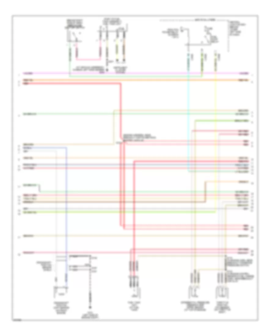
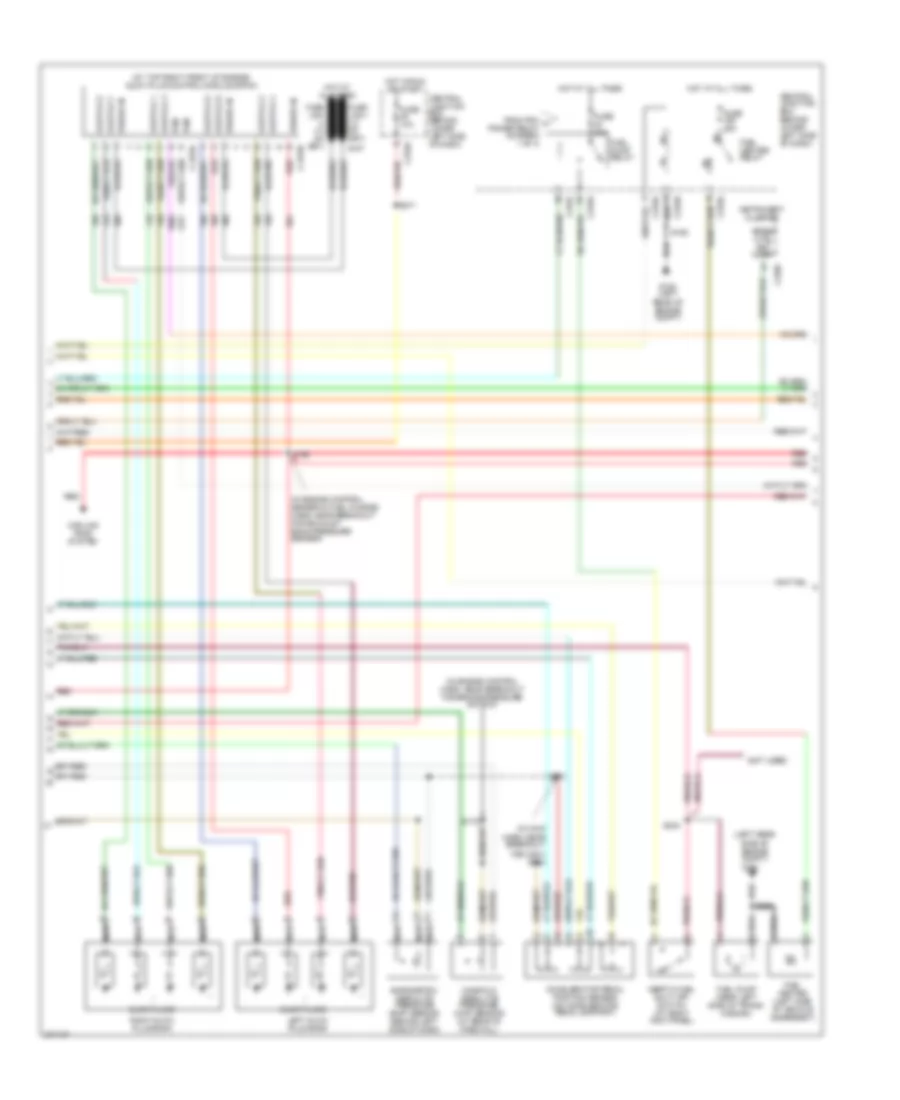
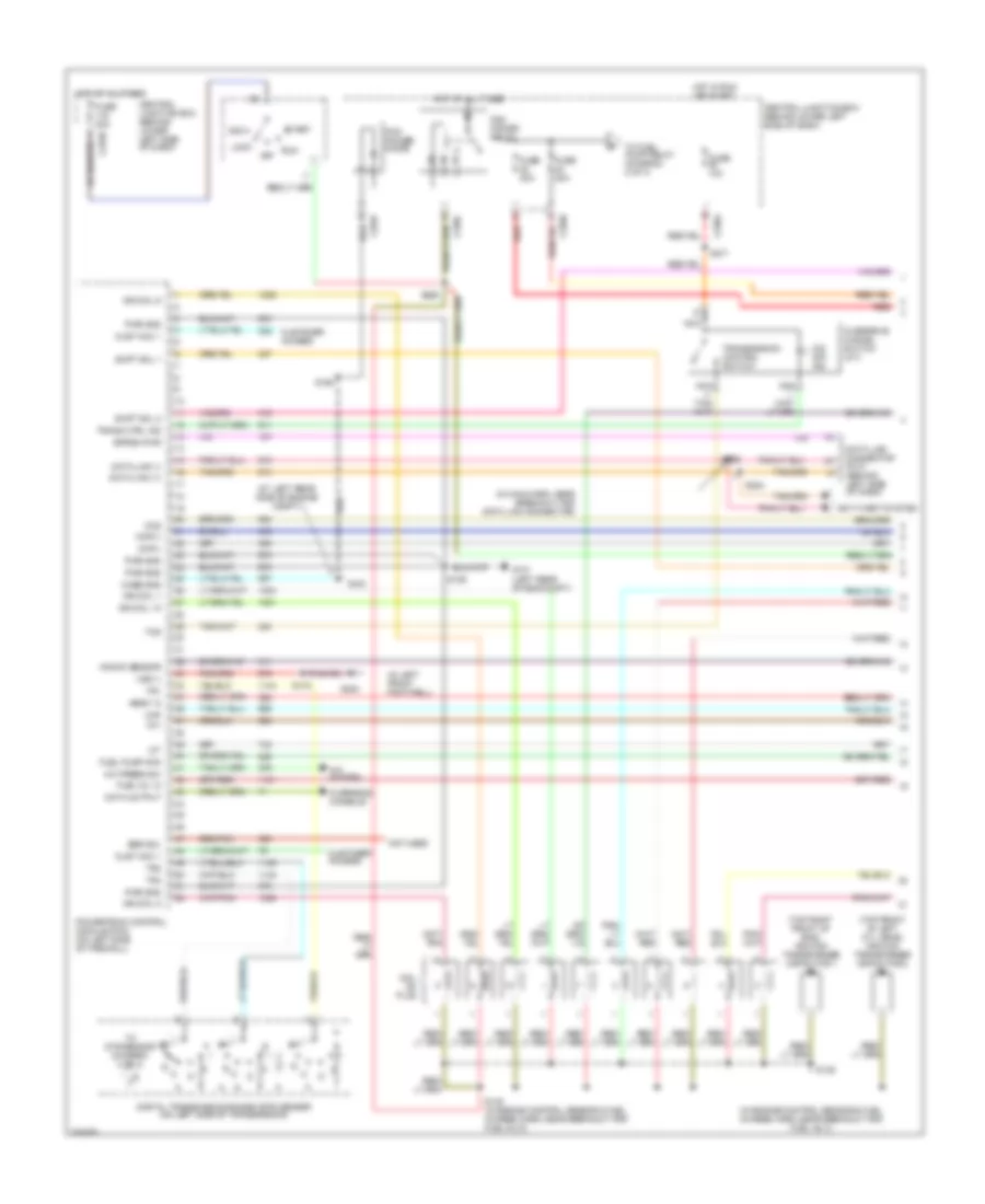
5.4L, Engine Performance Wiring Diagram (1 of 4) for Ford Excursion 2005

List of elements for 5.4L, Engine Performance Wiring Diagram (1 of 4) for Ford Excursion 2005:
- (in engine control sensor & fuel charge harn, near break- out for inj 3)
- (in main harn, near breakout for data link connector)
- (left rear side of engine compt)
- (not used)
- (under left side g300 of dash)
- A/c press sw
- A/c system
- Acc
- Anti-theft system
- C270a
- Ccs
- Central junction box (behind lower left side of dash)
- Ckp(+)
- Ckp(-)
- Coil on plug
- Cust access
- Customer access
- Data link (+)
- Data link (-)
- Data link connector (dlc) (behind left side of dash)
- Data output
- Diag grd
- Digital transmission range (dtr) sensor (on left side of transmission)
- Egr sol
- Fuel pump mon
- Fuse 10a
- Fuse 20a
- Fuse 30a
- G100
- G101 (left rear of engine compt)
- Hego 12
- Hot at all times
- Hot in run or start
- Iat
- Ign coil 1
- Ign coil 3
- Ign coil 5
- Ign coil 6
- Ignition transformer capacitor
- Ignition transformer capacitor (on rear of right cyl head)
- Knock sensor
- Lock
- Maf
- Nca
- Not used
- O/d off ind
- Off
- Overdrive cancel switch
- Overhead console
- Pcm power diode
- Pcm power relay
- Powertrain control module (pcm) (on left side of firewall)
- Pwr gnd
- R n
- Red
- Reprog pwr
- Run
- S106
- S130 (in engine control sensor & fuel charge harn, near break- out for inj 6)
- S135
- S162
- S201
- S258
- S271
- S284
- S286
- Shift sol 1
- Shift sol 2
- Start
- Tcs
- Tft
- To dtr sensor (diagram 4 of 4)
- To fuel pump relay (diagram 2 of 4)
- Tr1
- Tr2
- Tr4
- Trans ctrl ind
- Transmission control switch
- Vss (-)
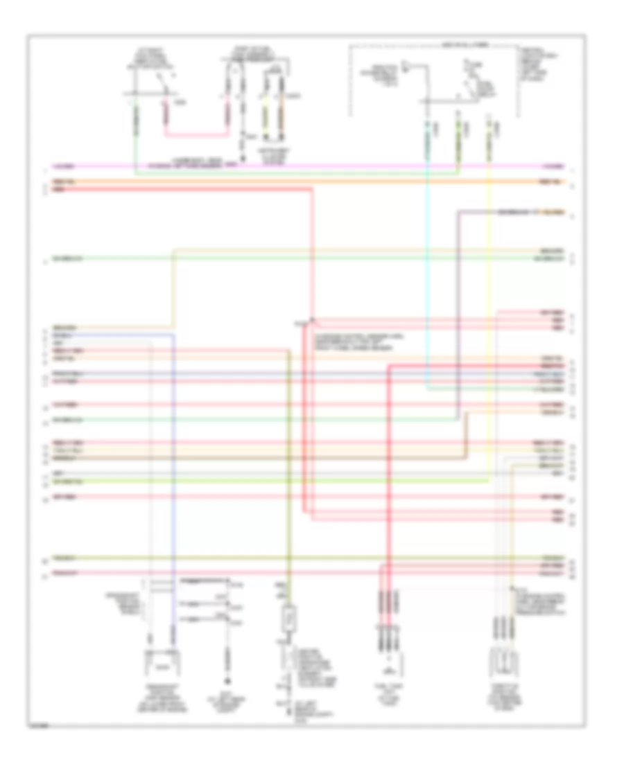
5.4L, Engine Performance Wiring Diagram (2 of 4) for Ford Excursion 2005
List of elements for 5.4L, Engine Performance Wiring Diagram (2 of 4) for Ford Excursion 2005:
- (behind right side of dash) inertia fuel shut-off switch
- (engine harness, near breakout for powertrain control module)
- (part of fuel tank assembly) fuel tank unit
- C270a
- C270f
- C270h
- Central junction box (behind lower left side of dash)
- Crankshaft position (ckp) sensor (on front engine)
- Crankshaft position sensor shield
- Differential pressure feedback egr (dpfe) sensor (at top of engine)
- From pcm power relay (diagram 1 of 4)
- Fuel pump relay
- Fuel tank unit (at fuel tank)
- Fuse 20a
- G101 (left side of engine compt)
- Hot at all times
- Instrument cluster system
- Nca
- Red
- Red/pnk
- S123
- S133 (in engine control sensor & fuel charge harn, near breakout for inj 6)
- S145
- S161
- S167
- S170 (in engine harn, near breakout for brake pressure switch)
- S401
- Throttle position (tp) sensor (on throttle body)
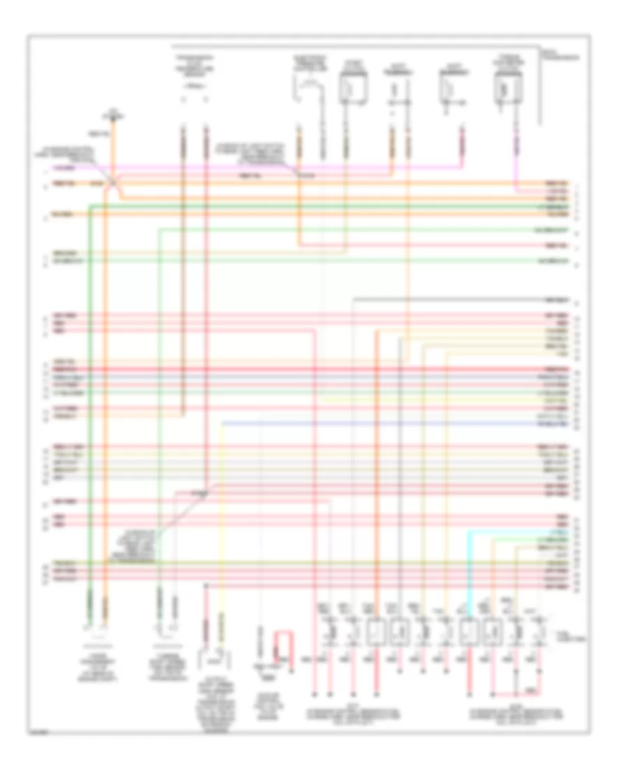
5.4L, Engine Performance Wiring Diagram (3 of 4) for Ford Excursion 2005
List of elements for 5.4L, Engine Performance Wiring Diagram (3 of 4) for Ford Excursion 2005:
- (at rear of engine compt)
- (in back-up light switch to rear light feed harn, near breakout for auto- matic transmission)
- (in back-up light switch to rear light feed harn, near breakout to transmission)
- (in engine control harn, near breakout for g100)
- (in engine control sensor & fuel charge harn, near breakout for plug on coil 3)
- (in engine control sensor & fuel charge harn, near breakout for plug on coil 7)
- 4r100 transmission
- A/c system
- Coast clutch solenoid
- Electronic pressure control solenoid
- Evr solenoid valve (at rear of engine)
- Fuel injectors
- Idle air control (iac) valve (on throttle body assembly)
- Output shaft speed (oss) sensor (4x2: at transmission) output shaft, 4x4: on top of transmission extension housing)
- Red
- Red/pnk
- S122
- S131
- S136
- S138
- S139
- Shift solenoid 1
- Shift solenoid 2
- Tan
- Tan/ red
- Tan/red
- Torque converter clutch solenoid
- Transmission fluid temperature sensor
- Turbine shaft speed (tss) sensor (on top of transmission)
- Vapor management valve
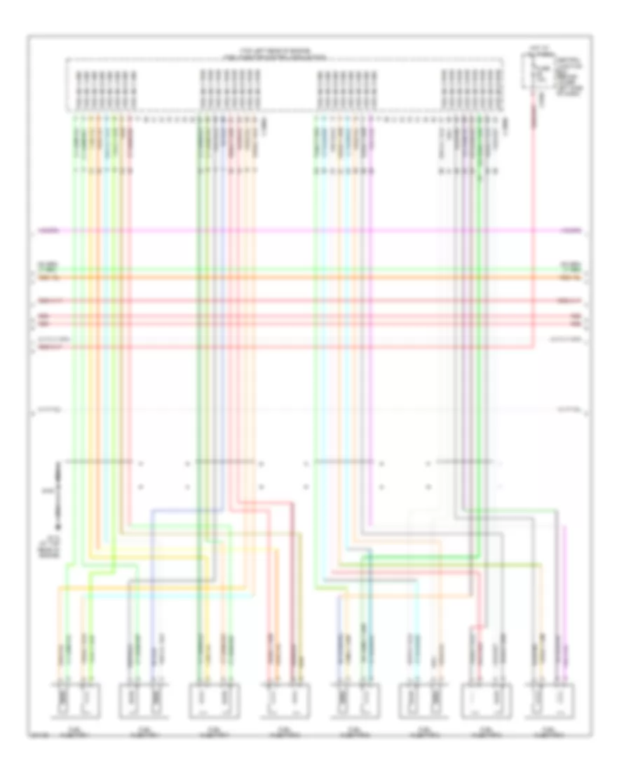
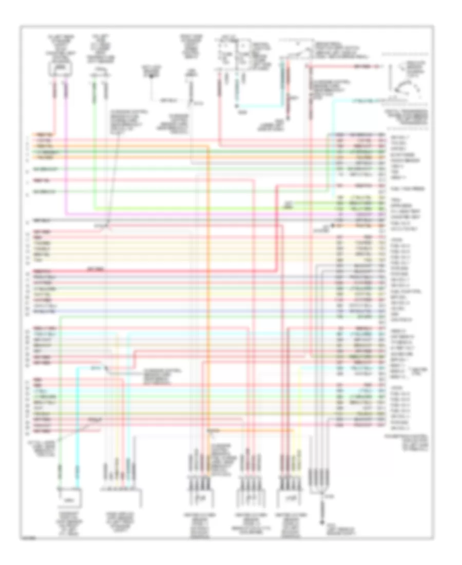
5.4L, Engine Performance Wiring Diagram (4 of 4) for Ford Excursion 2005
List of elements for 5.4L, Engine Performance Wiring Diagram (4 of 4) for Ford Excursion 2005:
- (engine control harn, near breakout for g101)
- (in engine control harn, near breakout for c1443)
- (in engine control harn, near breakout for g101)
- (in engine control sensor & fuel charge harn, near breakout for coil on plug 8)
- (in engine control sensor & fuel charge harn, near breakout for plug on coil 7)
- (in left rear of engine compt) evap canister vent control solenoid
- (in tail lamps harn, near breakout for c311)
- (not used)
- (on top left side of engine) cylinder head temperature (cht) sensor
- (right side of engine compt) speed control servo
- 5v ref volt
- A/c cltch rly
- A/c system
- Anti-lock brakes system
- Bpp sw
- Brake pedal position (bpp) switch (behind left side of dash, above brake pedal)
- C270a
- C270g
- Cam pos in
- Camshaft position (cmp) sensor (on front front of engine)
- Canister vent
- Central junction box (behind lower left side of dash)
- Cyl head temp
- Digital transmission range (dtr) sensor (on left side of transmission)
- Dpfe sens
- Epc sol
- From dtr sensor (diagram 1 of 4)
- Fuel inj 1
- Fuel inj 2
- Fuel inj 3
- Fuel inj 4
- Fuel inj 5
- Fuel inj 6
- Fuel inj 7
- Fuel inj 8
- Fuel pump ctrl
- Fuel tank press
- Fuse 10a
- G101 (left side of engine compt)
- G300 (under left side of dash)
- Heated oxygen sensor (ho2s) 11 (on right exhaust manifold)
- Heated oxygen sensor (ho2s) 12 (rear of catalytic converter)
- Heated oxygen sensor (ho2s) 21 (on left exhaust manifold)
- Heater ctrl
- Hego 11
- Hego 12
- Hego 21
- Hot at all times
- Iac sol
- Ign coil 2
- Ign coil 4
- Ign coil 7
- Ign coil 8
- Kap b(+)
- Knock sensor
- Knock sensor (on right cyl head)
- Maf sens in
- Mass airflow (maf) sensor (in left front of engine compt)
- Nca
- Not used
- Oss
- Powertrain control module (pcm) (on left side of firewall)
- Pwr gnd
- Red
- Red/pnk
- S106
- S114
- S115
- S132
- S134
- S228
- S343
- Sig return
- Tan
- Tan/red
- Tcc sol
- Tp sens in
- Tr3a (a/t)
- Tss
- Vapor valve
- Vpwr
- Vss (+)
- Vss input
6.0L DIESEL
6.0L Diesel, Engine Performance Wiring Diagram (1 of 5) for Ford Excursion 2005
List of elements for 6.0L Diesel, Engine Performance Wiring Diagram (1 of 5) for Ford Excursion 2005:
- (a/t)
- (bap) sens mon
- (behind left side of dash)
- (customer access)
- (engine control harn, near breakout for pcm)
- (in engine control harn, near breakout for c1047)
- (in engine control sensor harn, near breakout for g101)
- (in main harn, near breakout for dlc)
- (in main harn, near breakout to c210) s224
- (left rear of engine compt)
- (left rear of engine compt) g101
- (left rear side of engine) compt) g100
- (maf) sens out
- (map) sens mon
- (not used)
- (scp) data -
- (scp) data+
- A/c clutch input
- A/c clutch rly
- A/c system
- Abs control module (at left side of eng compt)
- Acc
- Apps monitor 1
- Apps monitor 2
- Apps monitor 3
- Apps ref volt 2
- Apps sig rtn 2
- Auxiliary relay box 5 (at left rear side of engine compt)
- Brake ped pos sw
- Brake pedal position (bpp) switch (behind left side of dash, above brake pedal)
- Brake press sw in
- Brake pressure switch (on brake master cylinder)
- C135
- C1381a
- C270a
- C270h red
- Can bus 1h
- Can bus 1l
- Central junction box (behind lower left side of dash)
- Chassis gnd
- Computer data lines system
- Cruise control system
- Cust acc tp sig
- Cust acc vss out
- Data link connector (dlc)
- Data output link
- Fuel pmp rly
- Fuel pump monitor
- Fuse 10a
- Fuse 20a
- Fuse 2a
- Fuse 30a
- Fuse 50a
- G101
- G300 (under left side of dash)
- Gen/bat ind
- Grd/load sw
- Hot at all times
- Hot in run
- Injector driver module power relay
- Intk air temp sens
- Lock
- Maf sens sig rtn
- Mass airflow (maf) sensor (in left front of eng compt)
- Mod prog sig
- Nca
- Off
- Overhead console
- Park brake switch (on park brake assembly)
- Park brk sw input
- Pcm power diode
- Pcm power relay
- Powertrain control module (pcm) (on left side of firewall)
- Pwr
- Pwr gnd
- Pwr in
- Red
- Ref volt
- Run
- S101
- S106
- S111
- S112 (in engine control harn, near breakout to pcm)
- S114
- S120 (in engine control sensor harn, near breakout for auxiliary relay box 5)
- S123
- S162
- S174
- S228
- S284
- S286
- Sig rtn
- Sig rtn spd ctrl
- Speed ctrl ind
- Speed ctrl sw in
- Start
- Start rly ctrl
- Starting/ charging system
- Starting/charging system
- Tach output
- To fuel pump relay (diagram 2 of 4)
- Tow/haul switch
- Vss input
- Water in fuel sens
- Water in fuel sensor (on inside of left frame rail)
6.0L Diesel, Engine Performance Wiring Diagram (2 of 5) for Ford Excursion 2005
List of elements for 6.0L Diesel, Engine Performance Wiring Diagram (2 of 5) for Ford Excursion 2005:
- (at top right front of engine) glow plug control module (gpcm)
- (in engine control harn, near breakout for brake pressure switch)
- (in engine control sensor & fuel charge harn, near breakout for exhaust back pressure sensor)
- (in main harn, near breakout
- (left rear side of engine compt)
- (not used)
- Accelerator pedal position sensor (on accelerator pedal support)
- Barometric absolute pressure (bap) sensor (behind left side of dash)
- C1273a
- C1273b
- C220c
- C270a
- C270f
- Central junction box (behind lower left side of dash)
- Cooling fans system
- Ctrl set lamp
- For c291) s223
- From pcm a power relay (diagram 1 of 4)
- Fuel heater (left side of vehicle underbody)
- Fuel heater relay
- Fuel pump (near left side of trans- mission)
- Fuel pump relay
- Fuse 10a
- Fuse 20a
- Fuse 30a
- G100
- G100 (left rear of engine compt)
- Glow plugs
- Glw plg 1
- Glw plg 2
- Glw plg 3
- Glw plg 4
- Glw plg 5
- Glw plg 6
- Glw plg 7
- Glw plg 8
- Hot at all times
- Hot in run or start
- Inertia fuel shut off switch (at right kick panel)
- Instrument cluster
- Left glow plug bank
- Manifold absolute pressure (map) sensor (at rear of firewall)
- Nca
- Pcm
- Power in
- Red
- Right glow plug bank
- S147
- S162
- S170
- S193
- S213
- S234
- S250
- S271
- Speed
6.0L Diesel, Engine Performance Wiring Diagram (3 of 5) for Ford Excursion 2005
List of elements for 6.0L Diesel, Engine Performance Wiring Diagram (3 of 5) for Ford Excursion 2005:
- (top left rear of engine) fuel injector control module (ficm)
- C1388a
- C1388b
- C270g
- Central junction box (behind lower left side of dash)
- Fuel inj 1 gnd
- Fuel inj 1 pwr
- Fuel inj 2 gnd
- Fuel inj 2 pwr
- Fuel inj 3 gnd
- Fuel inj 3 pwr
- Fuel inj 4 gnd
- Fuel inj 4 pwr
- Fuel inj 5 gnd
- Fuel inj 5 pwr
- Fuel inj 6 gnd
- Fuel inj 6 pwr
- Fuel inj 7 gnd
- Fuel inj 7 pwr
- Fuel inj 8 gnd
- Fuel inj 8 pwr
- Fuel injector 1
- Fuel injector 2
- Fuel injector 3
- Fuel injector 4
- Fuel injector 5
- Fuel injector 6
- Fuel injector 7
- Fuel injector 8
- Fuse 10a
- G110 (at top rear of engine)
- Hot at all times
- Nca
- Red red
- S194
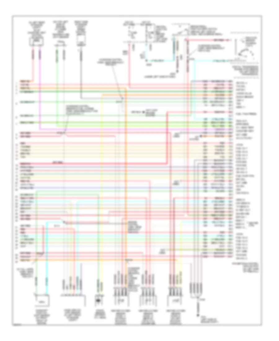
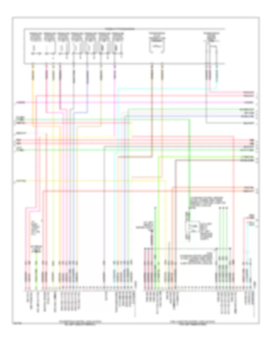
6.0L Diesel, Engine Performance Wiring Diagram (4 of 5) for Ford Excursion 2005
List of elements for 6.0L Diesel, Engine Performance Wiring Diagram (4 of 5) for Ford Excursion 2005:
- (at left rear of engine compt) g101
- (epc) sol 1 ctrl
- (epc) sol 2 ctrl
- (epc) sol 3 ctrl
- (epc) sol 4 ctrl
- (epc) sol 5 ctrl
- (epc) sol common
- (idm) pwr rly ctrl
- (in engine control sensor & fuel charge harn, near breakout for fuel injector control module)
- (in engine control sensor & fuel charge harn, near breakout for fuel injector control module) s196
- (iss) sens in
- (on left side of firewall)
- (oss) sens in
- (tcc) sol ctrl
- (tcil) ctrl
- (tft) sens
- (tft) sens in
- (tss) sens in
- (w/ elec- tronic shift on the fly)
- Auxiliary relay box 5 (at left rear side of engine compt)
- C1381b
- C1388c
- Can bus 2h
- Can bus 2l
- Communication
- Cylinder id
- Drain wire
- Exterior lights system
- Fuel del com
- Fuel injector control module (ficm) (top left rear of eng)
- Fuse 15a
- Line press sol
- Logic pwr
- Neutral sw sen
- Powertrain control module (pcm)
- Pressure control solenoid
- Pwr gnd
- Pwr in
- Red
- Red red
- Ref volt
- Rev lmp rly ctrl
- Rly ctrl bat feed
- S195
- Sig rtn
- Torqshift transmission
- Tran range sens
- Transmission fluid temperature sensor
- Transmission range sensor (trs)
6.0L Diesel, Engine Performance Wiring Diagram (5 of 5) for Ford Excursion 2005
List of elements for 6.0L Diesel, Engine Performance Wiring Diagram (5 of 5) for Ford Excursion 2005:
- (4x4: top of transmission extension housing) 4x2: at transmission output shaft) output shaft speed (oss) sensor
- (act) sens in
- (at turbo charge) variable geometric turbo actuator
- (ckp) sens +
- (ckp) sens -
- (cmp) sens +
- (cmp) sens -
- (ebp) sens sig
- (eot) sens in
- (icp) sens sig
- (idm) comm
- (idm) cyl id
- (idm) fuel del
- (in back-up light switch to rear light feed harn, near breakout for transmission)
- (in engine con- trol sensor & fuel charge harn, near breakout for manifold air temperature sensor)
- (in engine control sensor & fuel charge harn, in breakout for ficm)
- (ipr) ctrl
- (lower left front center of engine) camshaft position (cmp) sensor
- (lower right side of engine) crankshaft position (ckp) sensor
- (not used)
- (top left side of transmission) speed sensor assembly
- (top rear center of engine) injection pressure regulator
- C1381c
- C281b
- Can bus 2h
- Can bus 2l
- Cool temp sens
- Cooling fans system
- Egr temp sens
- Egr temperature sensor (top front of engine)
- Egr val pos sen
- Egr valve act
- Egr valve actuator (at top of engine)
- Elec fan cltch
- Engine coolant temperature (ect) sensor (on front of engine)
- Engine oil temperature (eot) sensor (top right of engine)
- Exhaust back pressure sensor (left front of engine)
- Fan sig rtn
- Fan spd sig
- Four- wheel drive control module (behind right side of dash)
- Glow plug sys
- Gnd drain wire
- Injection control pressure (icp) sensor (top left rear of engine)
- Intermediate shaft
- Manifold air temperature (mat) sensor (top left front of engine)
- Nca
- Powertrain control module (pcm) (on left side of firewall)
- Red
- Ref volt
- S127 (in back-up light switch to rear light feed harn, near breakout for c1385)
- S128
- S190
- S192
- S197
- Sig rtn
- Speed sensor
- Turbine shaft speed sensor
- Turbo vane ctrl
6.8L
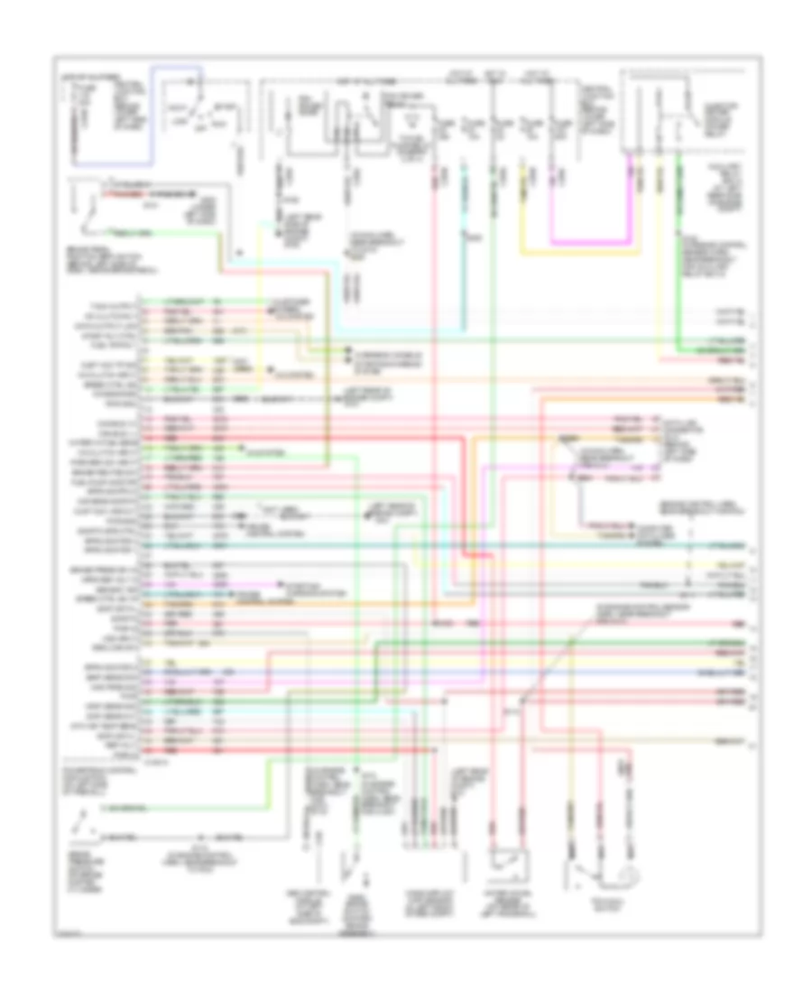
6.8L, Engine Performance Wiring Diagram (1 of 4) for Ford Excursion 2005
List of elements for 6.8L, Engine Performance Wiring Diagram (1 of 4) for Ford Excursion 2005:
- (at left rear side of engine compt)
- (in engine control sensor & fuel charge harn, near breakout for fuel inj 3)
- (in left front footwell)
- (in main harn, near breakout for data link connector)
- (top front of left cyl head) ignition transformer capacitor 2
- (top right front of eng) ignition transformer capacitor 1
- A/c press sw
- A/c system
- Acc
- Anti-theft system
- C270a
- Case gnd
- Ccs
- Central junction box (behind lower left side of dash)
- Ckp(+)
- Ckp(-)
- Coil on plug
- Cust acc 1
- Customer access
- Data link (+)
- Data link (-)
- Data link connector (dlc) (behind left side of dash)
- Data output
- Digital transmission range (dtr) sensor (on left side of transmission)
- Egr sol
- Eprom pwr
- Fuel inj 10
- Fuel pump mon
- Fuse 10a
- Fuse 20a
- Fuse 30a
- G100
- G101 (left rear of eng compt)
- G300
- Hego 12
- Hot at all times
- Hot in run or start
- Iat
- Ign coil 1
- Ign coil 10
- Ign coil 5
- Ign coil 6
- Knock sensor
- Lock
- Maf
- Nca
- Not used
- O/d off ind
- Off
- Overdrive cancel switch (a/t)
- Overhead console
- Pcm power diode
- Pcm power relay
- Powertrain control module (pcm) (on left side of firewall)
- Pwr gnd
- R n
- Red
- Run
- S106
- S130 (in engine control sensor & fuel charge harn, near breakout for fuel inj 6)
- S135
- S162
- S172
- S258
- S271
- S284
- S286
- Shift sol 1
- Shift sol 2
- Start
- Tcs
- Tft
- To dtr sensor (diagram 4 of 4)
- To fuel pump relay (diagram 2 of 4)
- Tr1
- Tr2
- Tr4
- Trans ctrl ind
- Transmission control switch
- Vss (-)
6.8L, Engine Performance Wiring Diagram (2 of 4) for Ford Excursion 2005
List of elements for 6.8L, Engine Performance Wiring Diagram (2 of 4) for Ford Excursion 2005:
- (at left rear of engine compt) g100
- (at right kick panel) inertia fuel shut-off switch
- (in engine control sensor harn, near breakout for left front wheel speed sensor)
- (part of fuel tank assembly) fuel tank unit
- (under body, rear chassis, left side member)
- C270a
- C270f
- C270h
- C282
- C4033
- Central junction box (behind lower left side of dash)
- Crankshaft position (ckp) sensor (on lower front center of engine)
- Crankshaft position sensor shield
- From pcm power relay (diagram 1 of 4)
- Fuel pump relay
- Fuel tank unit (at fuel tank)
- Fuse 20a
- G101 (at left rear of engine compt)
- G400
- Heated positive crankcase ventilation element (on right side valve cover)
- Hot at all times
- Instrument cluster system
- Nca
- Red
- Red/pnk
- S123
- S145
- S161
- S167
- S170 (in engine control harn, near break- out for brake pressure switch)
- S401
- Throttle position (tp) sensor (top center of eng)
6.8L, Engine Performance Wiring Diagram (3 of 4) for Ford Excursion 2005
List of elements for 6.8L, Engine Performance Wiring Diagram (3 of 4) for Ford Excursion 2005:
- (at rear of engine compt)
- (in back-up light switch to rear light feed harn, near breakout to transmission)
- (in engine control harn, near breakout for g100)
- 4r100 transmission
- A/c system
- Coast clutch solenoid
- Electronic pressure controller
- Fuel injectors
- Idle air control (iac) valve (to of engine)
- Output shaft speed (oss) sensor (4x2: at transmission output shaft, 4x4: on top of transmission extension housing)
- Red
- Red/pnk
- S122
- S131 (in engine control sensor & fuel charge harn, near breakout for coil on plug 7)
- S136 (in engine control sensor & fuel charge harn, near breakout for coil on plug 3)
- S138
- S139
- Shift solenoid 1
- Shift solenoid 2
- Tan
- Tan/ red
- Tan/red
- Torque converter clutch solenoid
- Transmission fluid temperature sensor
- Turbine shaft speed (tss) sensor (on top of transmission)
- Vapor management valve
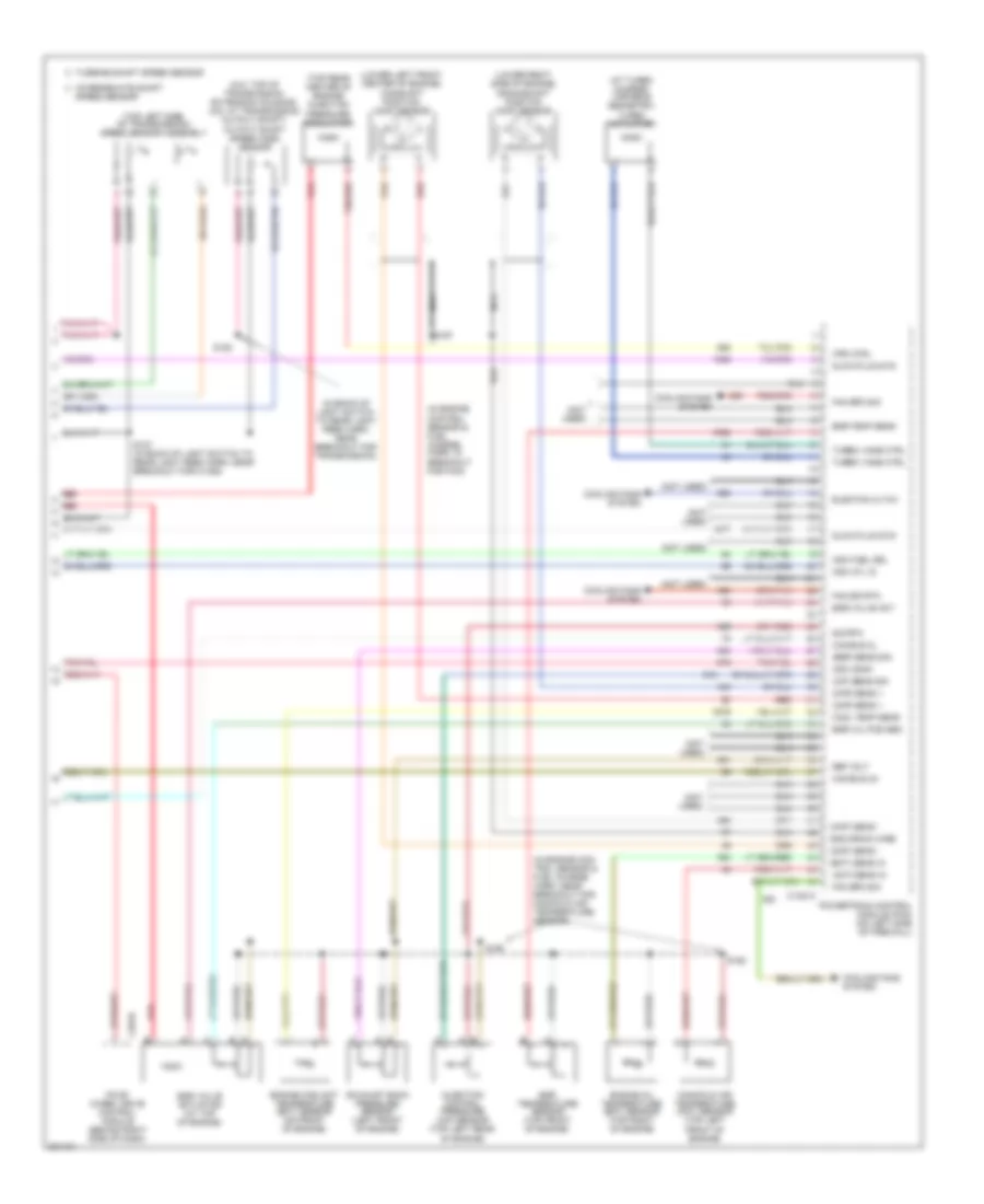
6.8L, Engine Performance Wiring Diagram (4 of 4) for Ford Excursion 2005
List of elements for 6.8L, Engine Performance Wiring Diagram (4 of 4) for Ford Excursion 2005:
- (in engine control sensor & fuel charge harn, near breakout for coil on plug 7)
- (in engine control sensor harn, near break- out for g101)
- (in engine control sensor harn, near breakout for g101)
- (in left rear of engine compt) evap canister vent control solenoid
- (in tail lamps harn, near breakout for c140)
- (on left side cyl head) cylinder head temperature (cht) sensor
- (on right exhaust manifold)
- (rear of catalytic converter)
- (right side of engine compt) speed control servo
- 5v ref volt
- A/c cltch rly
- A/c system
- Anti-lock brakes system
- Bpp sw
- Brake pedal position (bpp) switch (behind left side of dash, above brake pedal)
- C270a
- C270g
- Cam pos in
- Camshaft position (cmp) sensor (on front of left cyl head)
- Canister vent
- Central junction box (behind lower left side of dash)
- Cyl head temp
- Digital transmission range (dtr) sensor (on left side of transmission)
- Dpfe sens
- Epc sol
- Evap purge
- From dtr sensor (diagram 1 of 4)
- Fuel inj 1
- Fuel inj 2
- Fuel inj 3
- Fuel inj 4
- Fuel inj 5
- Fuel inj 6
- Fuel inj 8
- Fuel inj 9
- Fuel pump ctrl
- Fuel tank press
- Fuse 10a
- G101 (left rear of engine compt)
- G300 (under left side of dash)
- Heated oxygen sensor (ho2s) 11
- Heated oxygen sensor (ho2s) 12
- Heated oxygen sensor (ho2s) 21 (on left exhaust manifold)
- Heater ctrl
- Hego 11
- Hego 12
- Hego 21
- Hot at all times
- Iac sol
- Ign coil 3
- Ign coil 4
- Ign coil 7
- Ign coil 8
- Ign coil 9
- Kap b(+)
- Knock sensor
- Maf sens in
- Mass airflow (maf) sensor (in left front of engine compt)
- Nca
- Not used
- On plug 8)
- Oss
- Powertrain control module (pcm) (on left side of firewall)
- Pwr gnd
- Red
- Red/pnk
- S106
- S114
- S115
- S132
- S134
- S228
- S343
- Sig return
- Tan
- Tan/red
- Tcc sol
- Tp sens in
- Tr3a
- Tss
- Vpwr
- Vss (+)
- Vss input