ENGINE PERFORMANCE
4.0L
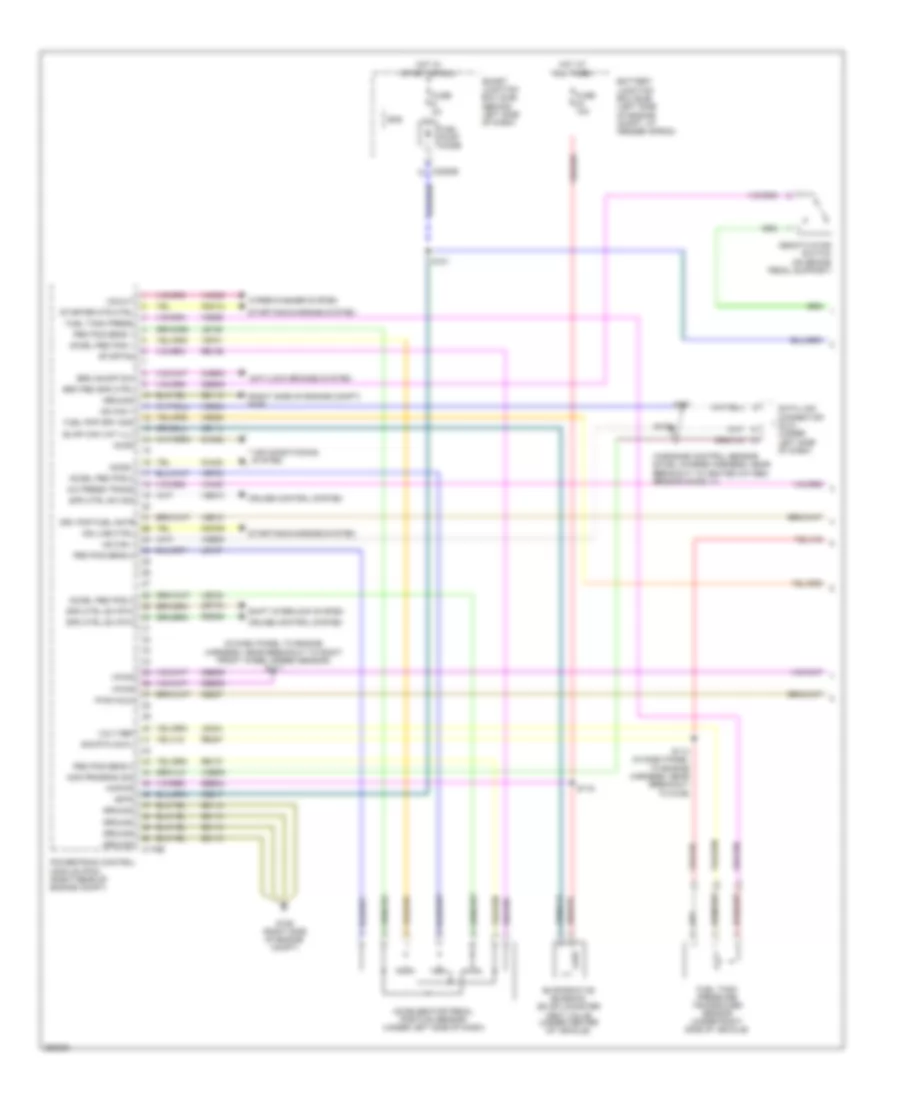
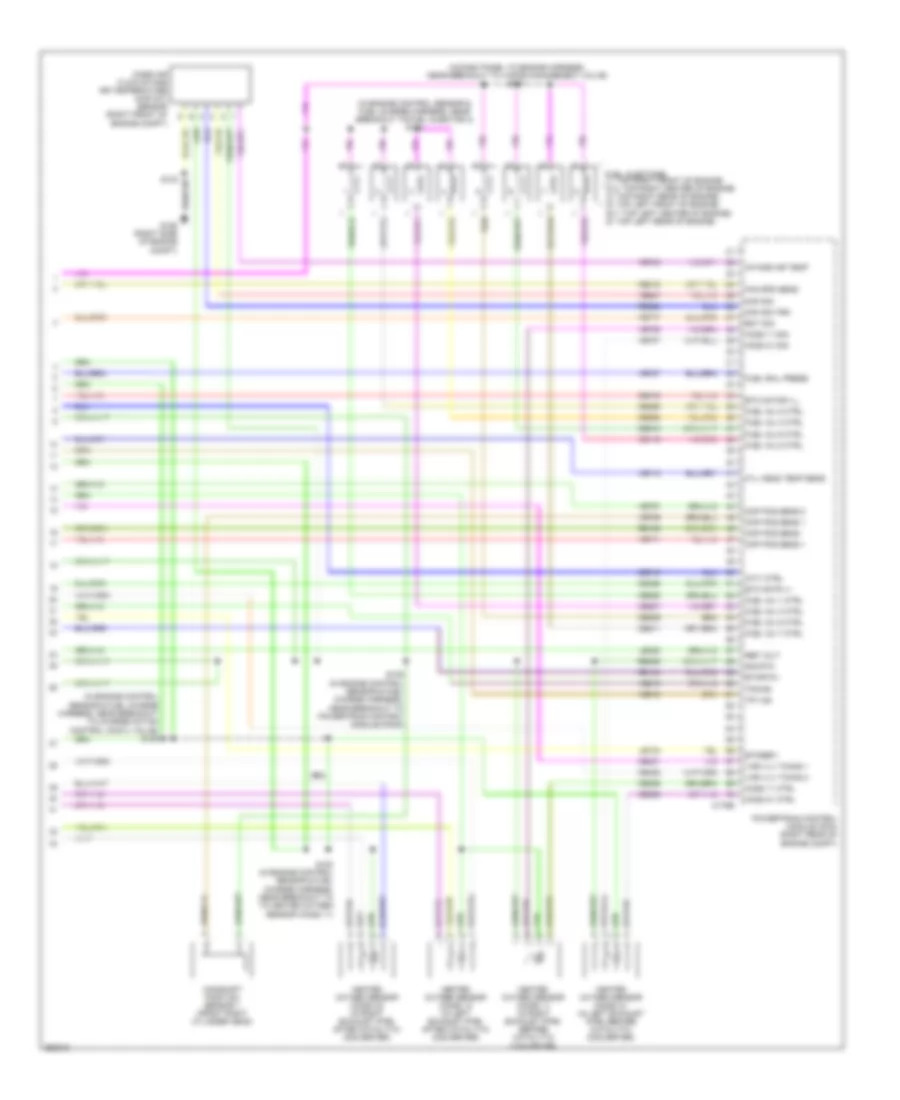
4.0L, Engine Performance Wiring Diagram (1 of 5) for Ford Explorer Sport Trac 2007

List of elements for 4.0L, Engine Performance Wiring Diagram (1 of 5) for Ford Explorer Sport Trac 2007:
- (in dash panel to engine harness, near breakout to left headlight)
- (in dash panel to engine harness, near breakout to left horn) s124
- (in dash panel to engine harness, near breakout to right front wheel speed sensor) s117
- (right side of engine compt) g106
- A/c press trans
- Accel ped pos 1
- Accel ped pos 2
- Accel ped pos 3
- Accelerator pedal position sensor (under left side of dash)
- Accr
- Accs
- Acds1
- Air conditioning system
- Anti-lock brakes system
- Battery junction box (bjb) (left side of engine compt, at fender apron)
- Brk on/off sw
- Brk ped spd ctrl
- C175b
- C2280e
- Cbb39
- Ccb08
- Ccs09
- Cdc09
- Cdc12
- Ce114
- Ce237
- Ce517
- Ces09
- Cet34
- Ch302
- Ch423
- Ch443
- Cruise control system
- Data link connector (dlc) (under left side of dash)
- Deactivator switch (on brake pedal support)
- Drv pmp fuel mntr
- Etcrtn2
- Evap can vnt vlv
- Evaporative emission (evap) canister vent valve (under center of vehicle)
- Fuel pmp drv mod
- Fuel pump diode
- Fuel tank press
- Fuel tank pressure transducer sensor (under right side of vehicle)
- Fuse 10a
- Fuse 2a
- G106 (right side of engine compt)
- Gd113
- Ground
- Hot at all times
- Hot in start or run
- Hs can +
- Hs can -
- Ind line ctrl
- Isp-r
- Kapwr
- Le136
- Le137
- Le424
- Mod program sig
- Ped pos sens 1
- Ped pos sens 2
- Ped pos sens 3
- Power steering pressure switch (top left front of engine)
- Powertrain control module (pcm) (right rear of engine compt)
- Pwr hold
- Re136
- Re137
- Re407
- Res08
- S114 (in dash panel to engine harness, near breakout to g106)
- S116
- S121
- S122
- Sbb24
- Shift interlock system
- Sig rtn cowl
- Smart junction box (sjb) (behind left side of dash)
- Sns
- Spd ctrl sw rtn
- Spd ctrl sw sig
- Starter mtr ctrl
- Starting/charging system
- Steering press sw
- Vdb04
- Vdb05
- Vdb09
- Ve225
- Ve518
- Ve701
- Ve702
- Ve703
- Ve922
- Ves10
- Vh433
- Vmc05
- Volt ref
- Vpwr
- Vs-out
- Wiper/washer system
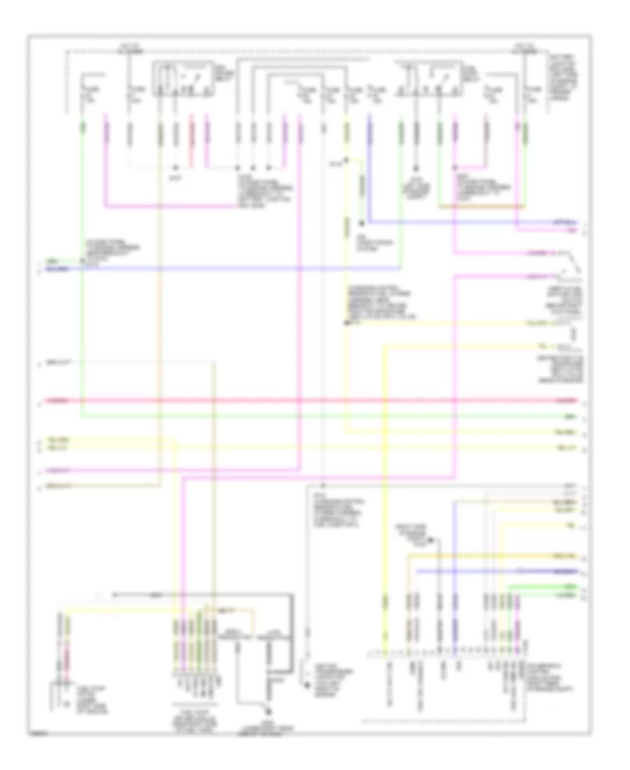
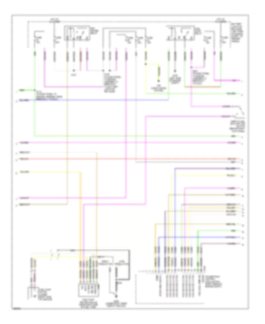
4.0L, Engine Performance Wiring Diagram (2 of 5) for Ford Explorer Sport Trac 2007
List of elements for 4.0L, Engine Performance Wiring Diagram (2 of 5) for Ford Explorer Sport Trac 2007:
- (in dash panel to engine harness, near breakout to g104) s118
- (in engine control sensor & fuel charge harness, near breakout to heated positive crankcase ventilation (pcv) valve) s113
- (right side of engine compt) g106
- A/c clt rly ctrl
- Air conditioning system
- Batt
- Battery junction box (bjb) (left side of engine compt, at fender apron)
- C175e
- C6a
- C6b
- C6c
- Ce123
- Ce124
- Ce125
- Ce132
- Ce321
- Ce515
- Ce911
- Cs gnd
- Early production
- Ect sen sig
- Evmv
- Fan ctrl variable
- Fp pwr
- Fpc
- Fpm
- Fpm rtn
- Fuel pump driver module (near right side of fuel tank)
- Fuel pump motor (under right side of vehicle)
- Fuel pump relay
- Fuel rail temp sig
- Fuse 15a
- Fuse 30a
- Fuse 40a
- G105 (left side of engine compt)
- G405 (under right rear
- Gd113
- Gd117
- Heated positive crankcase ventilation (pcv) valve (rear of engine)
- Hot at all times
- Ignition transformer capacitor (top left front of engine)
- Inertia fuel shutoff (ifs) switch (behind right kick panel)
- Late production
- Le111
- Md gnd
- Nca
- Pcm power relay
- Powertrain control module (pcm) (right rear of engine compt)
- Re515
- S103 (in engine control sensor & fuel charge harness, in breakout to fuel injector 3)
- S119
- S126 (in dash panel to engine harness, in breakout to battery junction box (bjb))
- S127
- S227 (in dash panel to engine harness, in breakout to c210)
- Side of vehicle)
- Vbpwr
- Ve225
- Ve518
- Ve716
- Ve728
- Vec03
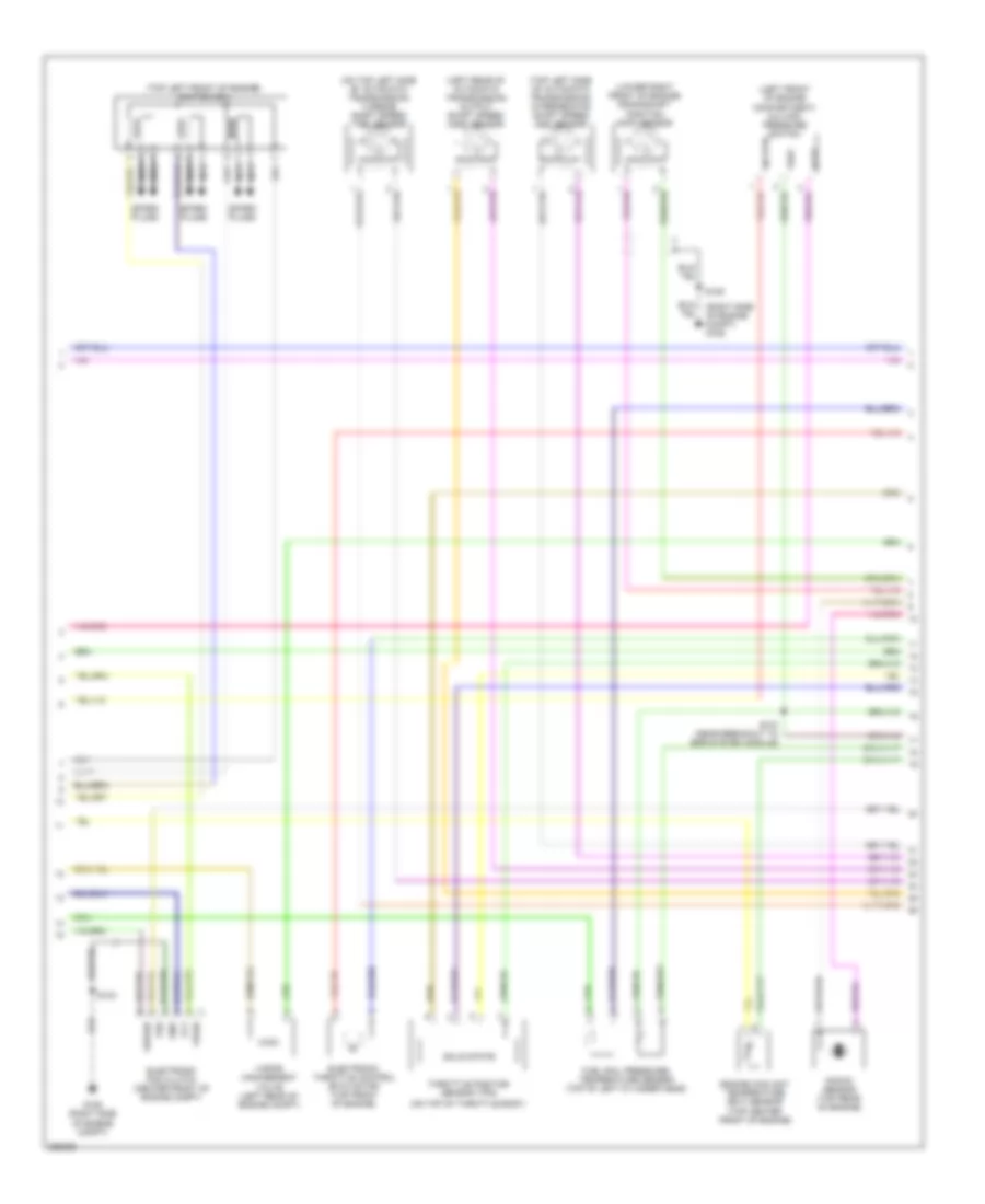
4.0L, Engine Performance Wiring Diagram (3 of 5) for Ford Explorer Sport Trac 2007
List of elements for 4.0L, Engine Performance Wiring Diagram (3 of 5) for Ford Explorer Sport Trac 2007:
- (left front of engine compartment) a/c high pressure switch
- (left rear of automatic transmission) output shaft speed (oss) sensor
- (lower right front of engine) crankshaft position (ckp) sensor
- (on top left side of automatic transmission) turbine shaft speed (tss) sensor
- (on top of throttle body)
- (right side of engine compt) g106
- (top center front of engine)
- (top left front of engine) ignition coil
- (top left side of automatic transmission) intermediate shaft speed (iss) sensor
- Acpt
- Electronic fan clutch (center front of engine compt)
- Electronic throttle control (etc) motor (top front of engine)
- Engine coolant temperature (ect) sensor
- Fcv
- Fss
- Fuel rail pressure/ temperature sensor (top of left cylinder head)
- G106 (right side of engine compt)
- Gnd
- Knock sensor (top rear of engine)
- Nca
- S103
- S107 (near breakout to egr system module)
- S109
- Sig rtn
- Solid state
- Spark plugs
- Throttle position sensor (tps)
- Vapor management valve (left rear of engine compt)
- Vbpwr
- Vpwr
- Vref
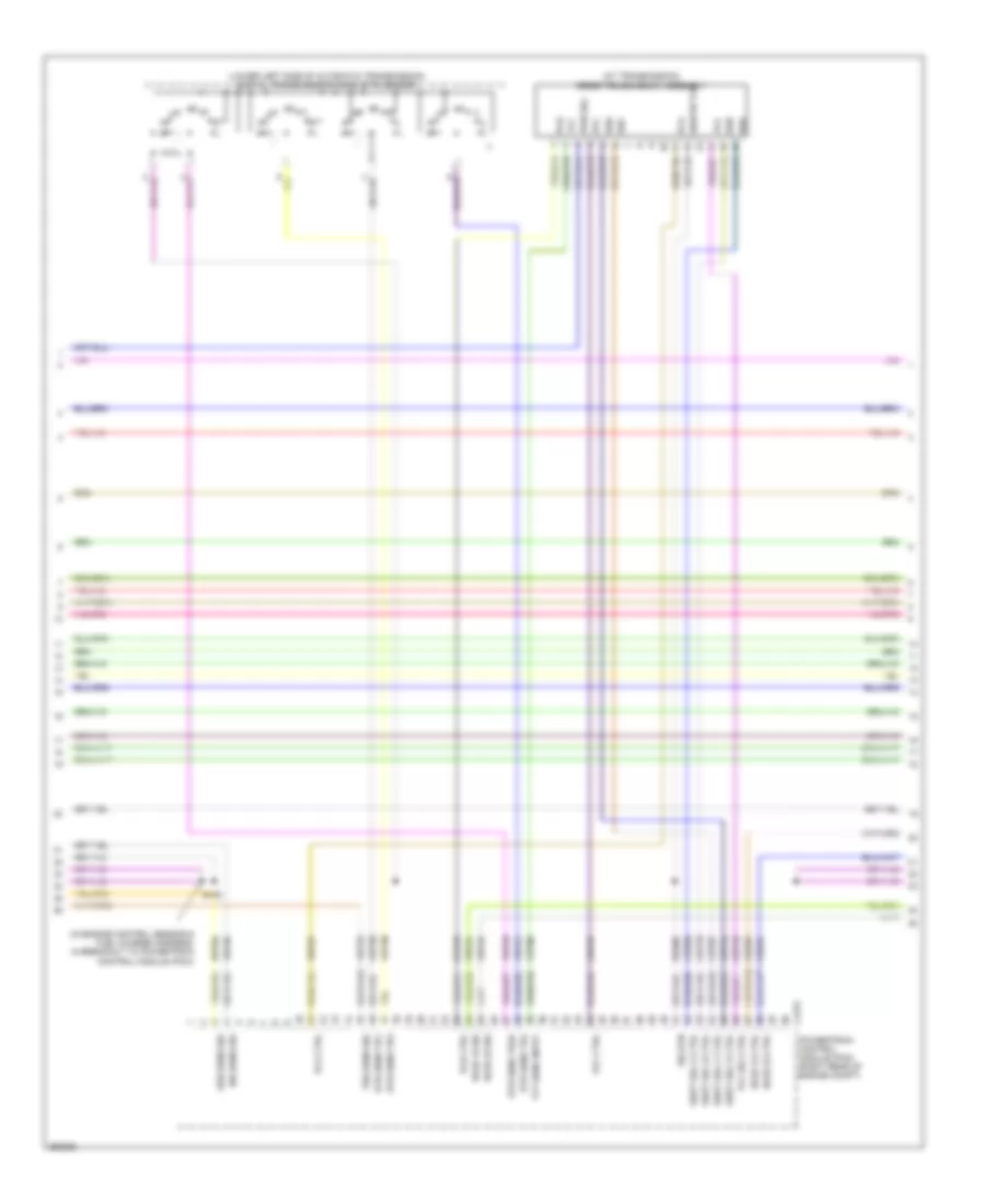
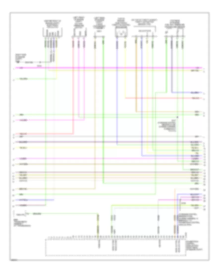
4.0L, Engine Performance Wiring Diagram (4 of 5) for Ford Explorer Sport Trac 2007
List of elements for 4.0L, Engine Performance Wiring Diagram (4 of 5) for Ford Explorer Sport Trac 2007:
- (at transmission) 5r55s transmission assembly
- (in engine control sensor & fuel charge harness, in breakout to powertrain control module (pcm))
- (lower left side of automatic transmission) digital transmission range (dtr) sensor
- C175t
- Ce233
- Ce234
- Ce418
- Cet05
- Cet06
- Cet07
- Cet18
- Cet19
- Cet44
- Cet45
- Dtr sens tr1
- Dtr sens tr2
- Dtr sens tr3a
- Dtr sens tr4
- Ho2s 12 ctrl
- Ho2s 12 sig
- Ho2s 22 ctrl
- Ho2s 22 sig
- Iss sens sig
- Oss sens sig
- Pca
- Pca ctrl
- Pcb
- Pcb ctrl
- Pcc
- Pcc ctrl
- Powertrain control module (pcm) (right rear of engine compt)
- Pwr sol
- Re406
- Ret04
- S106
- Shift sol a ctrl
- Shift sol b ctrl
- Shift sol c ctrl
- Shift sol d ctrl
- Sig rtn
- Sigrtn tft
- Ssa
- Ssb
- Ssc
- Ssd
- Tcc
- Tcc sol ctrl
- Tft
- Tft sens input
- Tss sens sig
- Ve731
- Ve733
- Ve739
- Vet27
- Vet28
- Vet29
- Vet30
- Vet31
- Vet33
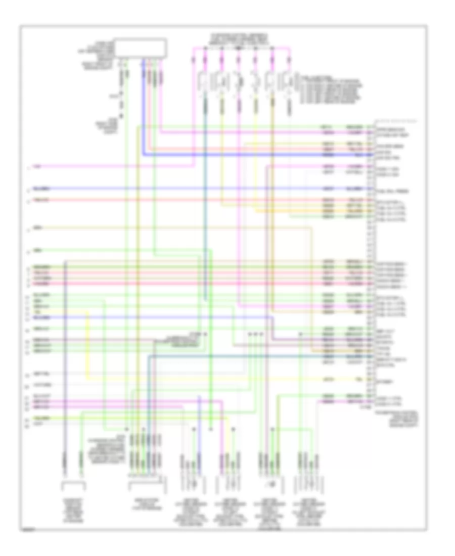
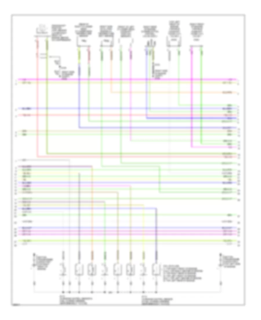
4.0L, Engine Performance Wiring Diagram (5 of 5) for Ford Explorer Sport Trac 2007
List of elements for 4.0L, Engine Performance Wiring Diagram (5 of 5) for Ford Explorer Sport Trac 2007:
- (in engine control sensor & fuel charge harness, near breakout to fuel injector 3) s104
- C175e
- Camshaft position sensor (top rear center of engine)
- Cbb42
- Ce133
- Ce205
- Ce206
- Ce207
- Ce208
- Ce209
- Ce210
- Ce235
- Ce236
- Ce412
- Ce426
- Ckp pos sens +
- Ckp pos sens -
- Cmp pos sens 1
- Dpfe sens sig
- Egr system module (top of engine)
- Egr syt mod in
- Etc motor +/_
- Etcref1
- Etcrtn1
- Evr ctrl
- Fan spd sens
- Fuel inj 1 ctrl
- Fuel inj 2 ctrl
- Fuel inj 3 ctrl
- Fuel inj 4 ctrl
- Fuel inj 5 ctrl
- Fuel inj 6 ctrl
- Fuel injectors (1: top right front of engine) (2: top right center of engine) (3: top right rear of engine) (4: top left front of engine) (5: top left center of engine) (6: top left rear of engine)
- Fuel rail press
- G106 (right side of engine compt)
- Heated oxygen sensor (ho2s) 11 (in right exhaust pipe, before catalytic converter)
- Heated oxygen sensor (ho2s) 12 (in left exhaust pipe, after catalytic converter)
- Heated oxygen sensor (ho2s) 21 (in left exhaust pipe, before catalytic converter)
- Heated oxygen sensor (ho2s) 22 (in right exhaust pipe, after catalytic converter)
- Ho2s 11 ctrl
- Ho2s 11 sig
- Ho2s 21 ctrl
- Ho2s 21 sig
- Intake air temp
- Knock sens 1 +
- Knock sens 1 -
- Le134
- Le423
- Maf sig
- Maf sig trn
- Mass air flow/intake air temperature (maf/iat) sensor (right front of engine compt)
- Powertrain control module (pcm) (right rear of engine compt)
- Re134
- Re135
- Re320
- Re323
- Re405
- Ref volt
- S100 (in engine control sensor & fuel charge harness, near breakout to to heated oxygen sensor (ho2s) 11)
- S103
- S105 (in breakout to powertrain control module (pcm))
- Sig rtn
- Tp1 ns
- Tp2-ps
- Ve706
- Ve711
- Ve713
- Ve727
- Ve735
- Ve737
- Ve740
- Ve801
- Ve803
- Ve807
- Ve818
- Ve819
- Vec10
4.6L
4.6L, Engine Performance Wiring Diagram (1 of 5) for Ford Explorer Sport Trac 2007
List of elements for 4.6L, Engine Performance Wiring Diagram (1 of 5) for Ford Explorer Sport Trac 2007:
- (in dash panel to engine harness, near breakout to right front wheel speed sensor) s117
- (in engine control sensor & fuel charge harness, near breakout to heated oxygen sensor (ho2s) 11)
- (right side of engine compt) g106
- A/c press trans
- Accel ped pos 1
- Accel ped pos 2
- Accel ped pos 3
- Accelerator pedal position sensor (under left side of dash)
- Accr
- Acds1
- Air conditioning system
- Anti-lock brakes system
- Battery junction box (bjb) (left side of engine compt, at fender apron)
- Brk on/off sw
- Brk ped spd ctrl
- C175b
- C2280e
- Cbb39
- Ccb08
- Cdc09
- Cdc12
- Ce114
- Ce237
- Ce517
- Ces09
- Cet34
- Ch302
- Ch423
- Cruise control system
- Data link connector (dlc) (under left side of dash)
- Deactivator switch (on brake pedal support)
- Drv pmp fuel mntr
- Etcrtn2
- Evap can vnt vlv
- Evaporative emission (evap) canister vent valve (under center of vehicle)
- Fuel pmp drv mod
- Fuel pump diode
- Fuel tank press
- Fuel tank pressure transducer sensor (under right side of vehicle)
- Fuse 10a
- Fuse 2a
- G106 (right side of engine compt)
- Gd113
- Ground
- Hot at all times
- Hot in start or run
- Hs can +
- Hs can -
- Ind line ctrl
- Isp-r
- Kapwr
- Le136
- Le137
- Le424
- Mod program sig
- Ped pos sens 1
- Ped pos sens 2
- Ped pos sens 3
- Powertrain control module (pcm) (right rear of engine compt)
- Pwr hold
- Re136
- Re137
- Re407
- Res08
- S101
- S102
- S114 (in dash panel to engine harness, near breakout to g106)
- S116
- S121
- Sbb24
- Shift interlock system
- Sig rtn cowl
- Smart junction box (sjb) (behind left side of dash)
- Sns
- Spd ctrl sw rtn
- Spd ctrl sw sig
- Starter mtr ctrl
- Starting/charging system
- Vdb04
- Vdb05
- Vdb09
- Ve225
- Ve518
- Ve701
- Ve702
- Ve703
- Ve922
- Ves10
- Vh433
- Vmc05
- Volt ref
- Vpwr
- Vs-out
- Wiper/washer system
4.6L, Engine Performance Wiring Diagram (2 of 5) for Ford Explorer Sport Trac 2007
List of elements for 4.6L, Engine Performance Wiring Diagram (2 of 5) for Ford Explorer Sport Trac 2007:
- Air conditioning system
- Batt
- Battery junction box (bjb) (left side of engine compt, at fender apron)
- C175e
- Ce132
- Ce303
- Ce304
- Ce305
- Ce306
- Ce307
- Ce308
- Ce309
- Ce310
- Ce515
- Ce911
- Coil on plug 1 ctrl
- Coil on plug 2 ctrl
- Coil on plug 3 ctrl
- Coil on plug 4 ctrl
- Coil on plug 5 ctrl
- Coil on plug 6 ctrl
- Coil on plug 7 ctrl
- Coil on plug 8 ctrl
- Early
- Evmv
- Fp pwr
- Fpc
- Fpm
- Fpm rtn
- Fuel pump driver module (near right side of fuel tank)
- Fuel pump motor (under right side of vehicle)
- Fuel pump relay
- Fuel rail temp sig
- Fuse 15a
- Fuse 30a
- Fuse 40a
- G105 (left side of engine compt)
- G405 (under right rear side of vehicle)
- Gd117
- Hi spd eng fan rly
- Hot at all times
- Inertia fuel shutoff (ifs) switch (behind right kick panel)
- Late
- Le111
- Md gnd
- Nca
- Pcm power relay
- Powertrain control module (pcm) (right rear of engine compt)
- Production
- Re515
- S118 (in dash panel to engine harness, near breakout to g104)
- S126 (in dash panel to engine harness, in breakout to battery junction box (bjb))
- S127
- S227 (in dash panel to engine harness, in breakout to c210)
- Vbpwr
- Ve225
- Ve518
- Ve728
- Vec03
4.6L, Engine Performance Wiring Diagram (3 of 5) for Ford Explorer Sport Trac 2007
List of elements for 4.6L, Engine Performance Wiring Diagram (3 of 5) for Ford Explorer Sport Trac 2007:
- (center front of engine compt) electronic fan clutch
- (in engine control sensor & fuel charge harness, in breakout to powertrain control module (pcm))
- (left front of engine compt) a/c high pressure switch
- (left rear of engine compt) vapor management valve
- (on top of throttle body) throttle position sensor (tps)
- (right side
- (top of engine) electronic throttle control (etc) motor
- (top rear of engine) fuel rail pressure transducer sensor
- 6r60 transmission assembly (at transmission)
- Acpt
- C175t
- Ce233
- Ce234
- Cet40
- Fcv
- Fss
- G106
- Gnd
- Ho2s 12 ctrl
- Ho2s 12 sig
- Ho2s 22 ctrl
- Ho2s 22 sig
- Of engine compt)
- Powertrain control module (pcm) (right rear of engine compt)
- Re406
- S103
- S106
- S107 (in engine control sensor & fuel charge harness, in breakout to c110)
- Sig rtn
- Solid state
- Trsw-pn
- Vbpwr
- Ve731
- Ve733
- Vpwr
- Vref
4.6L, Engine Performance Wiring Diagram (4 of 5) for Ford Explorer Sport Trac 2007
List of elements for 4.6L, Engine Performance Wiring Diagram (4 of 5) for Ford Explorer Sport Trac 2007:
- (front of left cylinder head) camshaft position sensor 2
- (rear of right cylinder head) cylinder-head temperature sensor
- (right front of engine) variable camshaft timing (vct) valve 1
- (right rear of engine) charge motion control valve (cmcv)
- (right side of engine compt) g106
- (right side of oil pan) engine oil temperature (eot) sensor
- (top left front of engine) variable camshaft timing (vct) valve 2
- Coil on plugs (1: top right front of engine) (2 & 3: top right center of engine) (4: top right rear of engine) (5: top left front of engine) (6 & 7: top left center of engine) (8: top left rear of engine)
- Crankshaft position (ckp) sensor (lower right front of engine, behind a/c compressor)
- Gnd
- Ignition transformer capacitor 1 (top right front of engine)
- Ignition transformer capacitor 2 (top left side of engine)
- Imrc
- S103
- S109
- S110 (in engine control sensor & fuel charge harness, near breakout to c139)
- S112 (in engine control sensor & fuel charge harness, near breakout to c133)
- Vpwr
4.6L, Engine Performance Wiring Diagram (5 of 5) for Ford Explorer Sport Trac 2007
List of elements for 4.6L, Engine Performance Wiring Diagram (5 of 5) for Ford Explorer Sport Trac 2007:
- (in dash panel to engine harness, near breakout to vapor management valve) s111
- (in engine control sensor & fuel charge harness, near breakout to charge motion control (cmcv) valve) s108
- (in engine control sensor & fuel charge harness, near breakout to fuel injector 3) s104
- C175e
- C2112
- Camshaft position sensor 1 (front right cylinder head)
- Ce205
- Ce206
- Ce207
- Ce208
- Ce209
- Ce210
- Ce211
- Ce235
- Ce236
- Ce315
- Ce412
- Ce421
- Ce422
- Ce426
- Ckp pos sens +
- Ckp pos sens -
- Cmp pos sens 1
- Cmp pos sens 2
- Cyl head temp sens
- Eot sig
- Etc mntr +/-
- Etc motor +/_
- Etcref1
- Etcrtn1
- Fan spd sens
- Fuel inj 1 ctrl
- Fuel inj 2 ctrl
- Fuel inj 3 ctrl
- Fuel inj 4 ctrl
- Fuel inj 5 ctrl
- Fuel inj 6 ctrl
- Fuel inj 7 ctrl
- Fuel inj 8 ctrl
- Fuel injectors (1: top right front of engine) (2,3: top right center of engine) (4: top right rear of engine) (5: top left front of engine) (6,7: top left center of engine) (8: top left rear of engine)
- Fuel rail press
- G106 (right side of engine compt)
- Heated oxygen sensor (ho2s) 11 (in right exhaust pipe, before catalytic converter)
- Heated oxygen sensor (ho2s) 12 (in left exhaust pipe, after catalytic converter)
- Heated oxygen sensor (ho2s) 21 (in left exhaust pipe, before catalytic converter)
- Heated oxygen sensor (ho2s) 22 (in right exhaust pipe, after catalytic converter)
- Ho2s 11 ctrl
- Ho2s 11 sig
- Ho2s 21 ctrl
- Ho2s 21 sig
- Imtv ctrl
- Intake air temp
- Le134
- Le423
- Maf sig
- Maf sig trn
- Mass air flow/intake air temperature (maf/iat) sensor (right front of engine compt)
- Powertrain control module (pcm) (right rear of engine compt)
- Re134
- Re135
- Re320
- Re405
- Ref volt
- S100 (in engine control sensor & fuel charge harness, near breakout to to heated oxygen sensor (ho2s) 11)
- S103
- S105 (in engine control sensor & fuel charge harness, near breakout to powertrain control module (pcm))
- Sig rtn
- Tp1 ns
- Tp2-ps
- Var vlv timing 1
- Var vlv timing 2
- Ve706
- Ve707
- Ve711
- Ve712
- Ve717
- Ve727
- Ve735
- Ve737
- Ve740
- Ve807
- Ve818
- Ve819
- Vec10