ENGINE PERFORMANCE
6.7L TURBO DIESEL
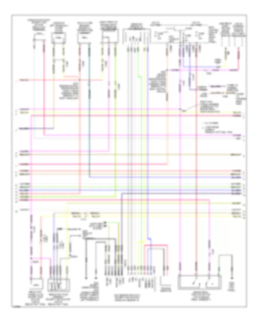
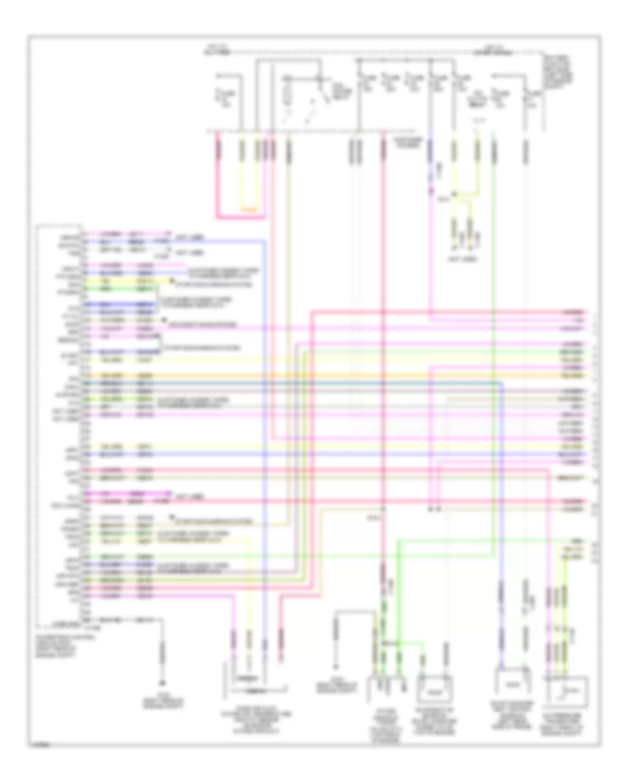
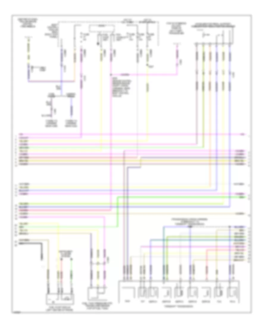
6.7L Turbo Diesel, Engine Performance Wiring Diagram (1 of 7) for Ford F-450 Super Duty XLT 2014

List of elements for 6.7L Turbo Diesel, Engine Performance Wiring Diagram (1 of 7) for Ford F-450 Super Duty XLT 2014:
- (customer access taped to harness near c210)
- (front passenger's rear view mirror assembly) (except w/ manual aero mirrors) ambient air temperature sensor
- Aat
- Accelerator pedal position sensor (accelerator pedal support)
- Accr
- Acpt
- Air conditioning system
- App
- App2
- Apprtn
- Apprtn2
- Appvref
- Appvref2
- Bcp lamp
- Bcp sw
- Bpp
- Bps
- C1232b
- C210
- C263
- C265
- C601
- C651
- C655
- Can2 high
- Can2 low
- Cbb33
- Cbb52
- Ccb08
- Cdc09
- Cdc12
- Cdc15
- Cdc35
- Cdc38
- Cdc47
- Cdc48
- Ce140
- Ce226
- Ce237
- Ce326
- Ce436
- Ce911
- Ce912
- Ce913
- Ce914
- Ce926
- Ce933
- Ces09
- Cet40
- Ch302
- Computer data lines system
- Cooling fans system
- Cto
- Digital
- Fc-v
- Fdsom
- Fpc
- Fpm
- Fss
- G103 (right rear of engine compt)
- Gd113
- Gencom
- Genmon
- Hs can+
- Hs can-
- Iat
- Isp-r
- Kapwr
- Le111
- Le136
- Le137
- Le424
- Le434
- Maf
- Mass air flow/intake air temperature sensor (on engine intake air duct)
- Nca
- Pcm wake
- Pcmrc
- Powertrain control module (pcm) (right rear of engine compt)
- Pt oil
- Pto
- Pto eng
- Pto ref
- Pto rpm
- Pto rtn
- Pwrgnd
- Re136
- Re137
- Re320
- Re327
- Re407
- S105
- Sbb72
- Sigrtn
- Smc
- Smrc
- Start
- Starting/ charging system
- Starting/charging system
- Transmissions system
- Trsw-pn
- Vbpwr
- Vdb04
- Vdb05
- Ve203
- Ve348
- Ve349
- Ve518
- Ve701
- Ve702
- Ve740
- Ve807
- Ve823
- Vec10
- Vh407
- Vh433
- Vmc05
- Vpwr
- Vref
- Vref 5v
- Vsout
- W/ power mirrors
- W/o power mirrors
- Wif
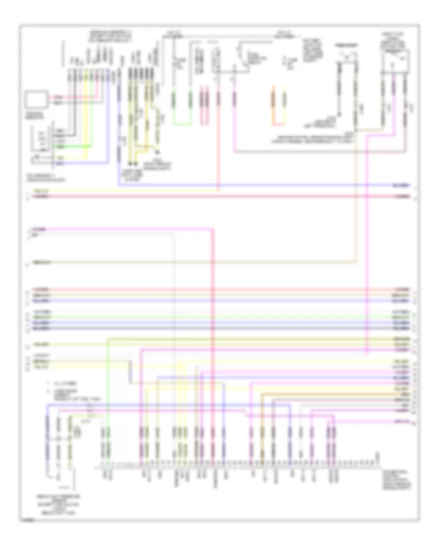
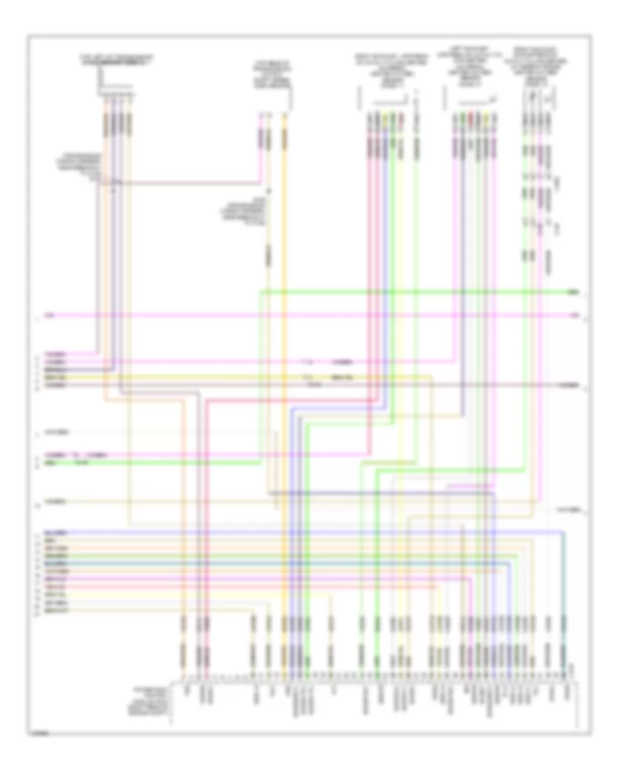
6.7L Turbo Diesel, Engine Performance Wiring Diagram (2 of 7) for Ford F-450 Super Duty XLT 2014
List of elements for 6.7L Turbo Diesel, Engine Performance Wiring Diagram (2 of 7) for Ford F-450 Super Duty XLT 2014:
- (body main wiring harness, in breakout to brake pedal position switch)
- (center of dash) trailer brake control module
- (middle of exhaust) (except high sulfur) reductant injector
- (middle of left frame rail) water- in-fuel sensor
- (near nox sensor 12) nox sensor 12
- (on oil filter bracket) engine oil temperature sensor
- (right front of engine compt) a/c pressure transducer
- (taped to harness near c422)
- (top of steering column) passive anti-theft transceiver
- 10a
- All others
- B00
- Body control module (bcm) (right kick panel)
- Brake pedal position switch (top of brake pedal assembly)
- C1046
- C110
- C139 c3047
- C1415
- C1581
- C210
- C2108
- C212
- C2280b
- C2280d
- C2280f
- C263
- C3047 c139
- C3611a
- C3611b
- C465
- Can2 +
- Can2 -
- Cbb36
- Ccb08
- Com
- Computer data lines system
- Crew chief
- Fuse
- G300 (left kick panel)
- G400 (rear of left frame rail)
- G401 (except narrow frame) g403 (narrow frame) (except narrow frame: middle of left frame rail)
- Gd180
- Gnd
- Heater +
- Heater -
- Hot at all times
- Ip1
- Ip2
- Memory +
- Memory -
- Micro
- Narrow frame
- Narrow frame w/ aft fuel tank
- Nca
- Nox sensor module 12 (except high sulfur) (near nox sensor 12)
- Pcm wake up (fet)
- Pnk
- Pwr gnd
- Rdpc
- Reductant pump assembly (except high sulfur) (top of reductant tank)
- Reductant purge valve (except high sulfur) (top of reductant tank)
- S100 (engine control sensor engine compt wiring harness, near breakout to right headlamp)
- S207
- S3000
- S3002
- S405
- Sig gnd
- Trimming resistor
- Ve348
- Ve349
- Vpwr
- Vs +
- Wide frame
- Wide frame/
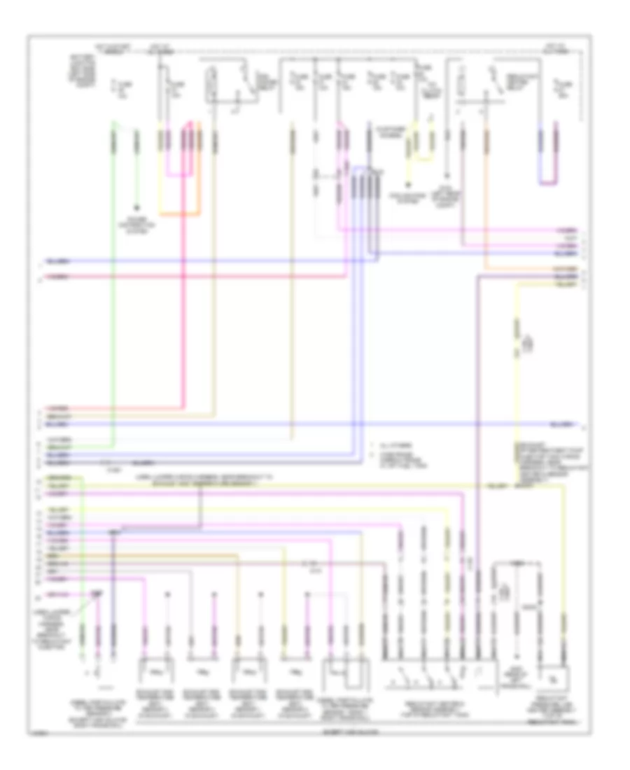
6.7L Turbo Diesel, Engine Performance Wiring Diagram (3 of 7) for Ford F-450 Super Duty XLT 2014
List of elements for 6.7L Turbo Diesel, Engine Performance Wiring Diagram (3 of 7) for Ford F-450 Super Duty XLT 2014:
- (near nox sensor 11) (except high sulfur) nox sensor module 11
- (right kick panel) inertia fuel shutoff (ifs) switch
- 20a
- All others
- Battery junction box (bjb) (left side of engine compt)
- C110
- C1232t
- C146
- C1581
- C211
- C3047 c139
- C3619a
- C3619b
- Can2 +
- Can2 -
- Cbb36
- Ce354
- Ce355
- Com
- Computer data lines system
- Dpf
- Dpf12
- Egt 11
- Egt 12
- Egt 13
- Egt 14
- Fuel pump
- Fuel pump (fp) motor diode
- Fuel pump (fp) relay
- Fuse
- Fuse 10a
- G103 (right rear of engine compt)
- G135 (center of left frame rail)
- Gd113
- Heater +
- Heater -
- Hot at all times
- Ip1
- Ip2
- Le425
- Le461
- Memory +
- Memory -
- Nca
- Nox sensor 11 (middle of exhaust)
- Pnk
- Powertrain control module (pcm) (right rear of engine compt)
- Pwr gnd
- Rdinjgnd
- Rdinjpwr
- Rdl1
- Rdl2
- Rdl3
- Rdlrtn
- Rdp
- Rdpc
- Rdpgc
- Rdt
- Re406
- Re839
- Reductant pressure sensor (except high sulfur) (top of reductant tank)
- S124 (engine control sensor engine compt wiring harness, near breakout to c1581)
- Sig gnd
- Sigrtn
- Trimming resistor
- Ve348
- Ve349
- Ve350
- Ve351
- Ve713
- Ve722
- Ve726
- Ve747
- Ve752
- Ve754
- Ve833
- Ve838
- Ve839
- Ve840
- Ve841
- Vpwr
- Vref
- Vs +
- Wide frame/ narrow frame w/ aft fuel tank
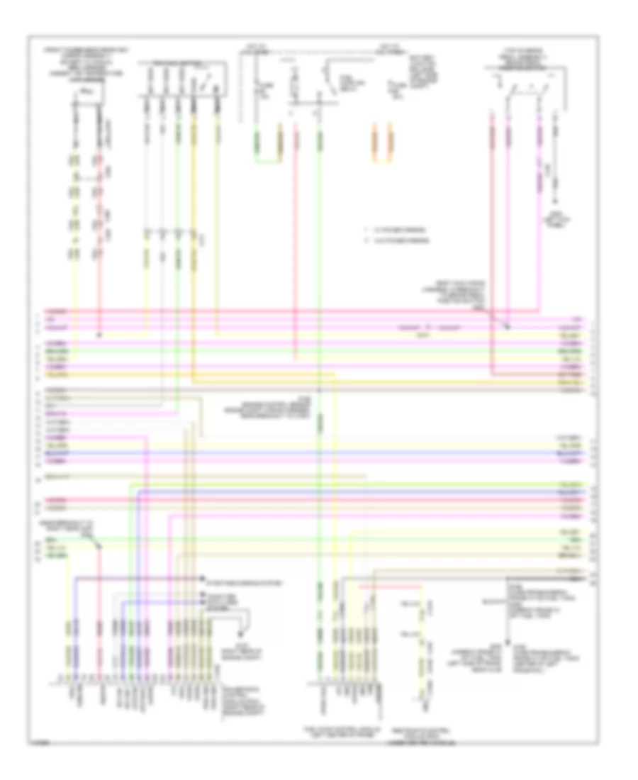
6.7L Turbo Diesel, Engine Performance Wiring Diagram (4 of 7) for Ford F-450 Super Duty XLT 2014
List of elements for 6.7L Turbo Diesel, Engine Performance Wiring Diagram (4 of 7) for Ford F-450 Super Duty XLT 2014:
- (customer access)
- (exhaust aftertreatment pump injector tank wiring harness, near breakout to reductant heater & sensor assembly) s3001
- (urea jumper wiring harness, near breakout to exhaust gas temperature sensor 1)
- (urea jumper wiring harness, near breakout to reductant injector)
- 10a
- A/c clutch relay
- All others
- Battery junction box (bjb) (left side of engine compt)
- C1047
- C110
- C139 c3047
- C1581
- Cooling fans system
- Diesel particulate filter pressure sensor 1 bank 1 (right frame rail)
- Diesel particulate filter pressure sensor 2 (except high sulfur) (right frame rail)
- Except high sulfur
- Exhaust gas temperature (egt) sensor 1 (in exhaust)
- Exhaust gas temperature (egt) sensor 2 (in exhaust)
- Exhaust gas temperature (egt) sensor 3 (in exhaust)
- Exhaust gas temperature (egt) sensor 4 (in exhaust)
- Fuse
- Fuse 10a
- Fuse 15a
- Fuse 25a
- Fuse n/a
- G104 (left rear of engine compt)
- G400 (rear of left frame rail)
- Hot at all times
- Hot in start or run
- Nca
- Pcm power relay
- Power distribution system
- Reductant heater & sensor assembly (top of reductant tank)
- Reductant heater relay
- Reductant pressure line heater assembly (top of reductant tank)
- S108
- S122
- S3002
- S405
- S408
- Wide frame/ narrow frame w/ aft fuel tank
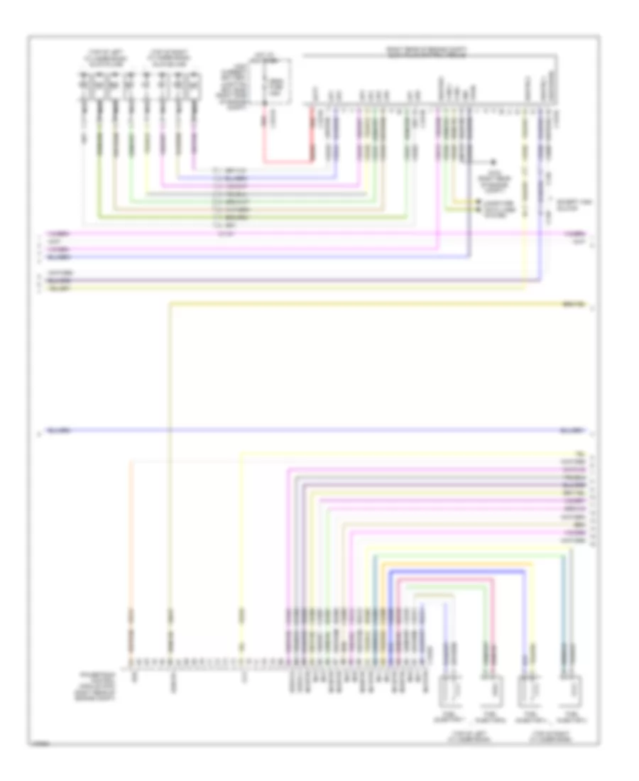
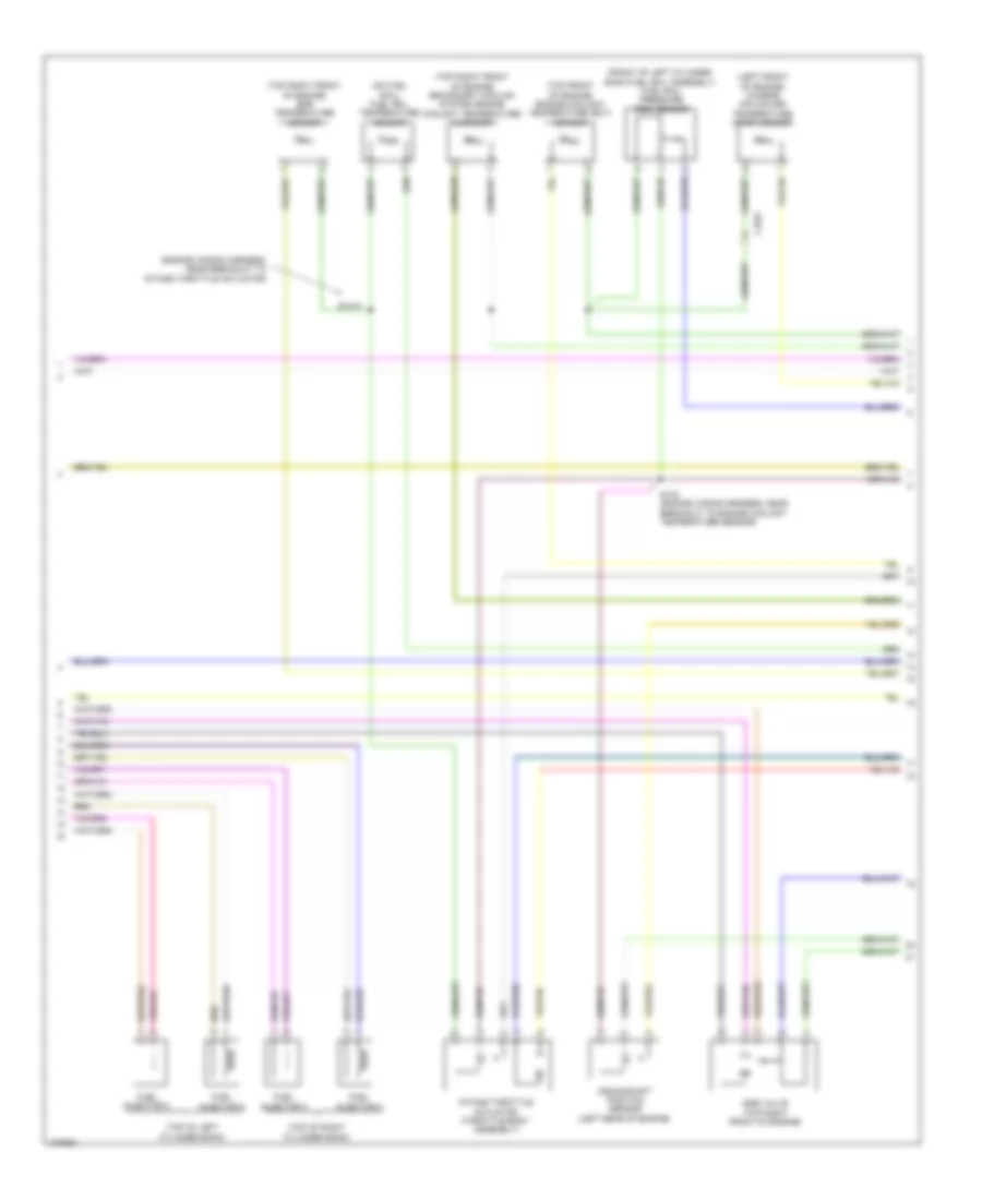
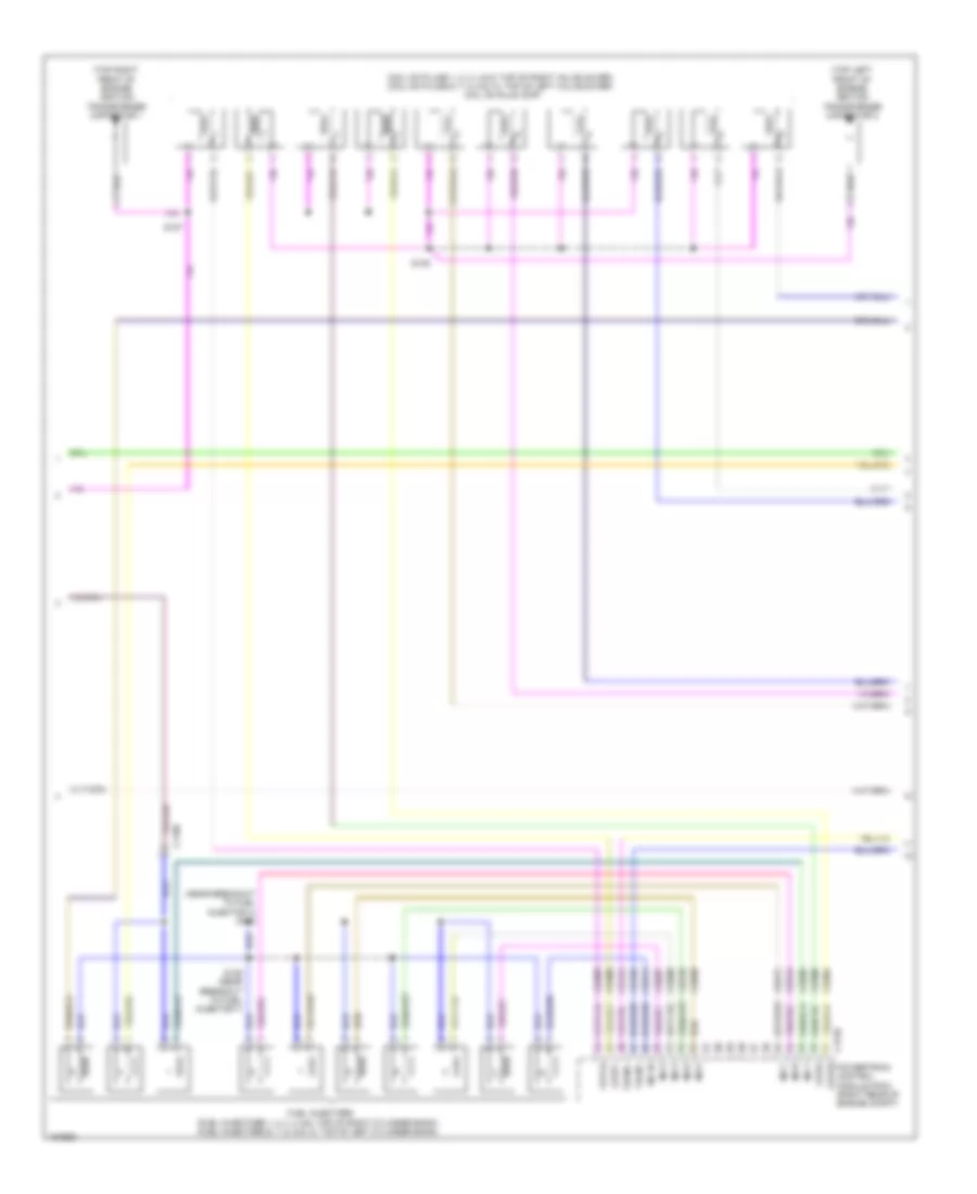
6.7L Turbo Diesel, Engine Performance Wiring Diagram (5 of 7) for Ford F-450 Super Duty XLT 2014
List of elements for 6.7L Turbo Diesel, Engine Performance Wiring Diagram (5 of 7) for Ford F-450 Super Duty XLT 2014:
- (right rear of engine compt) glow plug control module
- (top of left cylinder bank)
- (top of left cylinder bank) glow plugs
- (top of right cylinder bank)
- (top of right cylinder bank) glow plugs
- 125a
- Batt
- C110
- C1147
- C1232e
- C1273a
- C1273b
- C1273c
- C146
- C1617b
- Can2 +
- Can2 -
- Cbb36
- Ccv
- Ce101
- Ce102
- Ce205
- Ce206
- Ce207
- Ce208
- Ce209
- Ce210
- Ce211
- Ce212
- Ce243
- Ce244
- Ce245
- Ce246
- Ce247
- Ce248
- Ce251
- Ce252
- Ce352
- Ce356
- Ce513
- Ce609
- Computer data lines system
- Egr
- Egrcbv
- Egrvch
- Egrvcl
- Except high sulfur
- Fuel injector 1
- Fuel injector 4
- Fuel injector 6
- Fuel injector 7
- G103 (right rear of engine compt)
- Gd113
- Gnd
- Gp1
- Gp2
- Gp3
- Gp4
- Gp5
- Gp6
- Gp7
- Gp8
- High current battery junction box (bjb) (right side of engine compt)
- Hot at all times
- Inj1
- Inj1rtn
- Inj2
- Inj2rtn
- Inj3
- Inj3rtn
- Inj4
- Inj4rtn
- Inj5
- Inj5rtn
- Inj6
- Inj6rtn
- Inj7
- Inj7rtn
- Inj8
- Inj8rtn
- Mega fuse
- Nca
- Powertrain control module (pcm) (right rear of engine compt)
- Rdhtrc1
- Rdhtrc2
- Rdhtrpc
- Rdhtrpwr
- Re205
- Re206
- Re207
- Re208
- Re209
- Re210
- Re211
- Re212
- Red
- Sbf04
- Ve348
- Ve349
- Ve721
- Ve763
- Ve917
- Vpwr
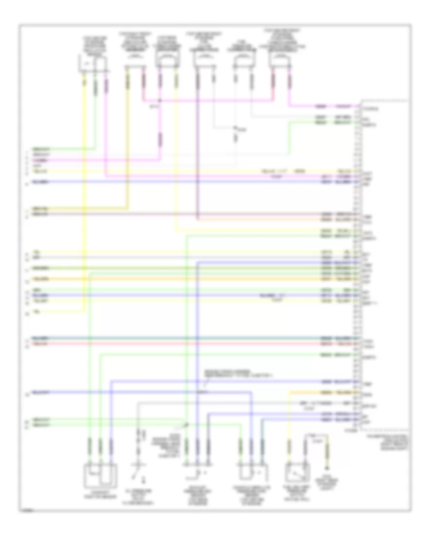
6.7L Turbo Diesel, Engine Performance Wiring Diagram (6 of 7) for Ford F-450 Super Duty XLT 2014
List of elements for 6.7L Turbo Diesel, Engine Performance Wiring Diagram (6 of 7) for Ford F-450 Super Duty XLT 2014:
- (engine wiring harness, near breakout to intake throttle actuator)
- (front of left cylinder bank fuel rail assembly) fuel rail pressure (frp) sensor
- (left front of engine) charge air cooler temperature (cact) sensor
- (on fuel rail) fuel rail temperature sensor
- (top front of engine) engine coolant temperature (ect) sensor
- (top of left cylinder bank)
- (top of right cylinder bank)
- (top right front of engine) egr temperature sensor
- (top right front of engine) secondary cooling system engine coolant temperature 2 sensor
- C1047
- Crankshaft position sensor (left rear of engine)
- Egr valve (top right front of engine)
- Fuel injector 2
- Fuel injector 3
- Fuel injector 5
- Fuel injector 8
- Intake throttle actuator (throttle body assembly)
- S1013
- S123 (engine wiring harness, near breakout to engine coolant temperature sensor)
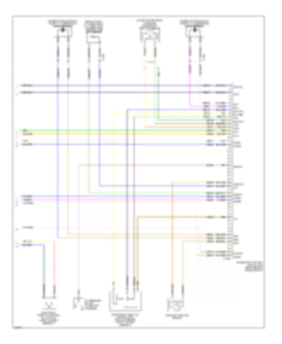
6.7L Turbo Diesel, Engine Performance Wiring Diagram (7 of 7) for Ford F-450 Super Duty XLT 2014
List of elements for 6.7L Turbo Diesel, Engine Performance Wiring Diagram (7 of 7) for Ford F-450 Super Duty XLT 2014:
- (engine wiring harness, near breakout to fuel injector 1)
- (top center front of engine) (if equipped) turbocharger wastegate regulating valve solenoid
- (top center front of engine) fuel volume control valve
- (top center of engine) crankcase ventilation sensor
- (top rear of engine) turbocharger actuator
- (top right front of engine) egr cooler bypass valve solenoid
- C1046
- C1047
- C1232e
- Cact
- Camshaft position sensor
- Ce256
- Ce257
- Ce412
- Ce426
- Ce435
- Ce460
- Ce932
- Ckp
- Cmc24
- Cmp
- Ect
- Ect2
- Egrt 11
- Eop sw
- Eot
- Exhaust pressure (ep) sensor (top rear of engine)
- Fdps
- Fpc
- Frp
- Frt
- Fuel delivery pressure switch (on fuel rail)
- Fuel pressure control valve
- Fvcv
- G103 (right rear of engine compt)
- Le111
- Le152
- Le423
- Le458
- Manifold absolute pressure (map) sensor (top center of engine)
- Map
- Oil pressure switch (on oil filter bracket)
- Powertrain control module (pcm) (right rear of engine compt)
- Re405
- S1002 (engine wiring harness, near breakout to fuel injector 1)
- S109
- S110
- S111
- Sigrtn
- Tacm+
- Tacm-
- Tcwrvs
- Ve701
- Ve716
- Ve718
- Ve726
- Ve727
- Ve728
- Ve736
- Ve755
- Ve759
- Ve803
- Ve820
- Vgtc
- Vref
6.8L
6.8L, Engine Performance Wiring Diagram (1 of 6) for Ford F-450 Super Duty XLT 2014
List of elements for 6.8L, Engine Performance Wiring Diagram (1 of 6) for Ford F-450 Super Duty XLT 2014:
- (customer access taped to harness near c210)
- (customer access)
- (not used)
- 10a
- A/c clutch relay
- A/c pressure transducer (right front of engine compt)
- Aat
- Accr
- Acpt
- Air conditioning system
- App rtn
- App1
- App2
- Appvref
- Battery junction box (bjb) (left side of engine compt)
- Bpp
- Bps
- C1148
- C1168
- C1220
- C1581
- C175b
- Canv
- Case gnd
- Cbb52
- Ccb08
- Cdc12
- Cdc15
- Cdc35
- Cdc38
- Ce114
- Ce237
- Ce326
- Ce436
- Ce608
- Ce912
- Ce913
- Ce914
- Ce933
- Ces09
- Cet21
- Cet42
- Cet43
- Ch302
- Cls05
- Cto
- Digital
- Evap canister vent control solenoid (left rear side of frame)
- Evaporative emission (evap) canister purge valve (top of engine)
- Fc-v
- Fpc
- Fpm
- Fss
- Fuse
- Fuse 10a
- Fuse 15a
- Fuse 20a
- Fuse n/a
- G103 (right rear of engine compt)
- Gd113
- Genmon
- Gnd
- Hot at all times
- Hot in start or run
- Iat
- Imtv
- Injpwrm
- Intake manifold tuning valve (imtv) (top front of engine)
- Isp-r
- Le111
- Le136
- Maf
- Mass air flow/ intake air temperature (maf/iat) sensor (on engine intake air duct)
- Not used
- Pcm power relay
- Pcm wake
- Pcmrc
- Powertrain control module (pcm) (right rear of engine compt)
- Pt oil
- Pto
- Pto eng
- Ptorpm
- Re136
- Re320
- S101
- S104
- S112
- Sig rtn
- Smc
- Smrc
- Start
- Starting/charging system
- Tron
- Trop
- Vbpwr
- Ve203
- Ve225
- Ve518
- Ve701
- Ve702
- Ve740
- Ve807
- Vec10
- Vh407
- Vh433
- Vmc05
- Vpwr
- Vref 5v
- Vsout
6.8L, Engine Performance Wiring Diagram (2 of 6) for Ford F-450 Super Duty XLT 2014
List of elements for 6.8L, Engine Performance Wiring Diagram (2 of 6) for Ford F-450 Super Duty XLT 2014:
- (body main wiring harness, in breakout to brake pedal position switch) s207
- (front passenger's rearview mirror assembly) (except w/ manual aero mirrors) ambient air temperature (aat) sensor
- (near breakout to right headlamp) s100
- (top of brake pedal assembly) brake pedal position switch
- Apprtn2
- Appvref2
- Battery junction box (bjb) (left side of engine compt)
- C1415
- C1581
- C175b
- C210
- C211
- C263
- C265
- C310a
- C601
- C651
- C655
- Cbb33
- Cdc10
- Ce515
- Ce608
- Computer data lines system
- Cr167
- Ens
- Fpc
- Fpm
- Fppwr
- Fprtn
- Ftp
- Fuel pump (fp) relay
- Fuel pump control module (left center of frame)
- Fuse 10a
- Fuse 20a
- G103 (right rear of engine compt)
- G136 (wide frame/narrow frame w/ mid fuel tank) (center of left frame rail)
- G300 (left kick panel)
- G402 (narrow frame w/ aft fuel tank) (left side of frame, near axle)
- Gd113
- Gd177
- Gencom
- Gnd
- Hot at all times
- Hs can +
- Hs can -
- Kapwr
- Le137
- Le230
- Le424
- Nca
- Not used
- Powertrain control module (pcm) (right rear of engine compt)
- Pwr gnd
- R/s
- Re137
- Re407
- Re515
- Restraints control module (rcm) (under center console)
- S156 (engine control sensor engine compt wiring harness, near breakout to c1581)
- Sbb72
- Sigrtn
- Starting/charging system
- Tow haul switch
- Tows
- Vdb04
- Vdb05
- Ve225
- Ve518
- Ve922
- Vpwr
- Vpwr fuel
- Vref
- W/ power mirrors
- W/o power mirrors
6.8L, Engine Performance Wiring Diagram (3 of 6) for Ford F-450 Super Duty XLT 2014
List of elements for 6.8L, Engine Performance Wiring Diagram (3 of 6) for Ford F-450 Super Duty XLT 2014:
- (accelerator pedal support) accelerator pedal position sensor
- (center of dash) trailer brake control (tbc) module
- (taped to harness near c422)
- (taped to harness near c465)
- (top of steering column) passive anti-theft transceiver
- (transmission wiring harness, in breakout to torqshift transmission) s183
- Body control module (bcm) (right kick panel)
- Boo
- C1415
- C1581
- C210
- C2108
- C212
- C2280b
- C2280d
- C2280f
- C263
- C465
- Crew chief
- Fuel pump (fet)
- Fuel pump module (left center of frame)
- Fuel tank pressure (ftp) transducer sensor (top of fuel tank)
- Fuse 10a
- Fuse 5a
- Hot at all times
- Hot in start or run
- Instrument cluster system
- Micro
- Narrow frame
- Nca
- Pc-a
- Pcm wake up (fet)
- S200 (engine control sensor engine compt wiring harness, near breakout to body control module)
- S227
- Sspc-a
- Sspc-b
- Sspc-c
- Sspc-d
- Sspc-e
- Tcc
- Tft
- Torqshift transmission
- Tr-p
- Wide frame
6.8L, Engine Performance Wiring Diagram (4 of 6) for Ford F-450 Super Duty XLT 2014
List of elements for 6.8L, Engine Performance Wiring Diagram (4 of 6) for Ford F-450 Super Duty XLT 2014:
- (left exhaust,
- (right exhaust, downstream of catalytic converter) (w/ narrow frame) heated oxygen sensor (ho2s) 12
- (right exhaust, upstream of catalytic converter) universal heated oxygen sensor (ho2s) 11
- (top left of transmission) speed sensor assembly
- (top rear of transmission) output shaft speed (oss) sensor
- (transmission wiring harness, near breakout to c145) s184
- C145
- C1581
- C175t
- Cat15
- Ce235
- Ce236
- Ce239
- Cet05
- Cet06
- Cet07
- Cet08
- Cet09
- Cet22
- Cet25
- Cet49
- Cet50
- Ho2s12
- Htr12
- Iss
- Le111
- Le448
- Le449
- Le450
- Le451
- Le452
- Le453
- Nca
- Oss
- Pc-a
- Powertrain control module (pcm) (right rear of engine compt)
- Re242
- Re406
- Red
- Ret04
- Ret24
- S185 (transmission wiring harness, near breakout to c145)
- Sigrtn
- Sspc-a
- Sspc-b
- Sspc-c
- Sspc-d
- Sspc-e
- Tcc
- Tft
- Tows
- Tr-p
- Tss
- Uo2s11
- Uo2s21
- Uo2sgref11
- Uo2sgref21
- Uo2shtr11
- Uo2shtr21
- Uo2spc11
- Uo2spc21
- Uo2spct11
- Uo2spct21
- Upstream of catalytic converter) universal heated oxygen sensor (ho2s) 21
- Vbpwr
- Ve744
- Ve745
- Ve826
- Ve827
- Vet27
- Vet33
- Vpwr
6.8L, Engine Performance Wiring Diagram (5 of 6) for Ford F-450 Super Duty XLT 2014
List of elements for 6.8L, Engine Performance Wiring Diagram (5 of 6) for Ford F-450 Super Duty XLT 2014:
- (coil on plugs 1, 2, 3, 4 & 5: top of right valve cover) (coil on plugs 6, 7, 8, 9 & 10: top of left valve cover) coil on plug (cop)
- (near breakout to fuel injector 4) s132
- (top left front of engine) ignition transformer capacitor 2
- (top right front of engine) ignition transformer capacitor 1
- C1168
- C175e
- Ce205
- Ce206
- Ce207
- Ce209
- Ce210
- Ce211
- Ce212
- Ce214
- Ce303
- Ce304
- Ce306
- Ce309
- Ce412
- Ce426
- Cop1a
- Cop2e powertrain control module (pcm) (right rear of engine compt)
- Cop4i
- Cop7f
- Fuel injectors (fuel injectors 1, 2, 3, 4 & 5: top of right cylinder bank) (fuel injectors 6, 7, 8, 9 & 10: top of left cylinder bank)
- Inj-1
- Inj-10
- Inj-2
- Inj-3
- Inj-5
- Inj-6
- Inj-7
- Inj-8
- S127
- S135
- S136 (near breakout to fuel injector 7)
- Tacm +
- Tacm -
6.8L, Engine Performance Wiring Diagram (6 of 6) for Ford F-450 Super Duty XLT 2014
List of elements for 6.8L, Engine Performance Wiring Diagram (6 of 6) for Ford F-450 Super Duty XLT 2014:
- (lower center front of engine) crankshaft position sensor
- (rear of right cylinder head) cylinder head temperature (cht) sensor
- (under intake manifold, in left cylinder bank) knock sensor 2
- (under intake manifold, in right cylinder bank) knock sensor 1
- C1163
- C175e
- Camshaft position sensor
- Ce113
- Ce208
- Ce213
- Ce305
- Ce307
- Ce308
- Ce310
- Ce311
- Ce312
- Ce316
- Cht
- Ckp+
- Ckp-
- Cmc24
- Cmp1
- Cop10d
- Cop3g
- Cop5c
- Cop6b
- Cop8h
- Cop9j
- De135
- Electronic throttle control (etc) motor (throttle body assembly)
- Electronic throttle control (etc) position sensor (throttle body assembly)
- Eop-sw
- Etc ref
- Etc rtn
- Evapcp
- Imtv
- Inj-4
- Inj-9
- Ks1+
- Ks1-
- Ks2+
- Ks2-
- Le134
- Oil pressure switch (lower left of engine)
- Powertrain control module (pcm) (right rear of engine compt)
- Re134
- Re135
- Re323
- Re324
- Re405
- Re429
- Shd rtn
- Sigrtn
- Tp1
- Tp2
- Ve706
- Ve711
- Ve712
- Ve801
- Ve802
- Ve818
- Ve819
- Vrs rtn