ENGINE PERFORMANCE
1.6L TURBO
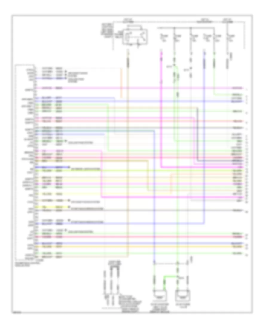
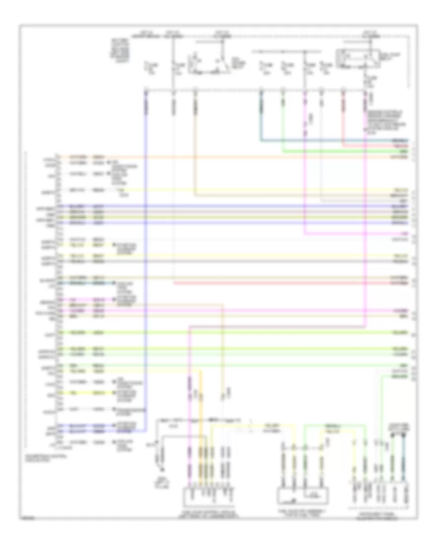
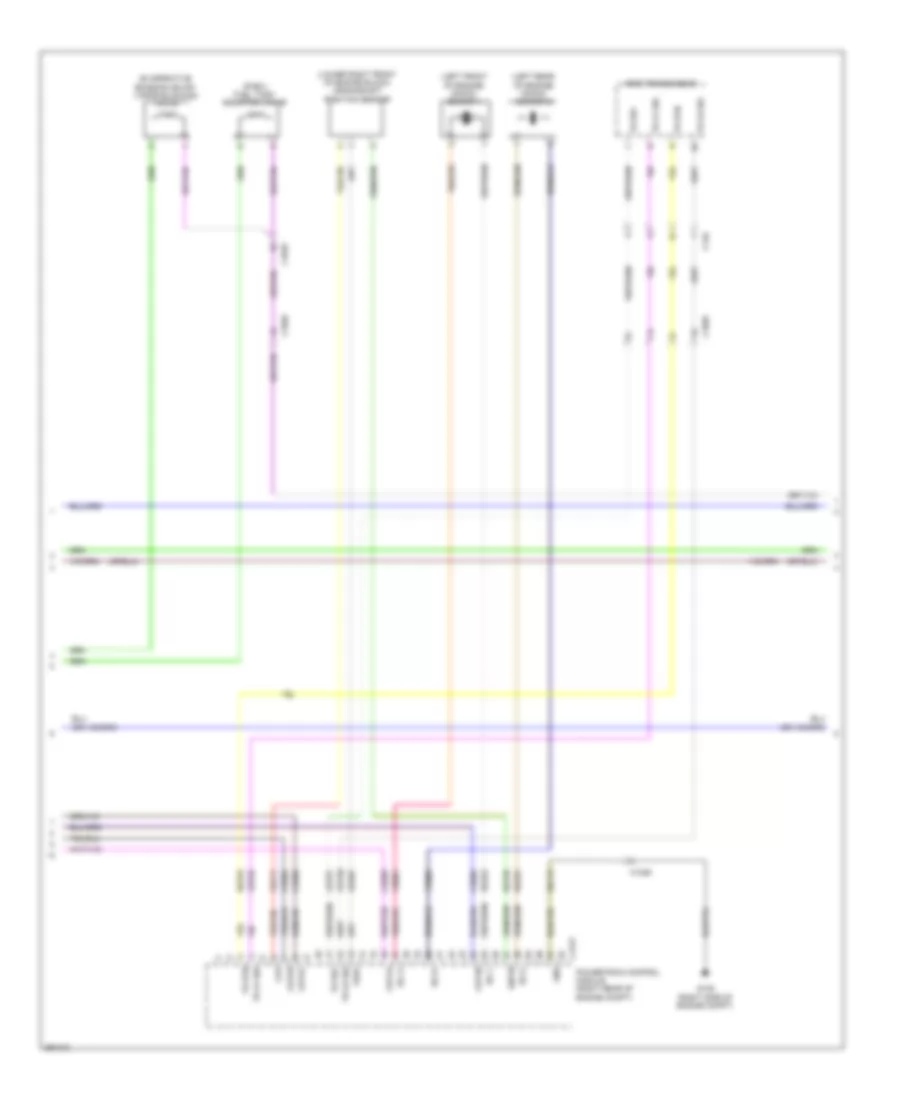
1.6L Turbo, Engine Performance Wiring Diagram, A/T (1 of 6) for Ford Fusion S 2013

List of elements for 1.6L Turbo, Engine Performance Wiring Diagram, A/T (1 of 6) for Ford Fusion S 2013:
- (engine controls sensor harness, near breakout to anti-lock brake system module) s120
- 10a
- Accr
- Air conditioning system
- Apprtn1
- Apprtn2
- Appvref1
- Appvref2
- Battery junction box (bjb) (left side of engine compt)
- C1010
- C1026
- C1035a
- C1035b
- C1232b
- C215
- C219
- C248
- C315
- Cact
- Canv
- Cbb26
- Cdc12
- Cdc15
- Cdc35
- Ce113
- Ce114
- Ce170
- Ce233
- Ce436
- Ce515
- Ce608
- Cec01
- Cec02
- Ch302
- Ch307
- Computer data lines system
- Cooling fans system
- Cpc
- Cr115
- Dc to dc converter control module (w/ auto start/ stop system) (right rear of engine compt)
- Eng start sig
- Evapcp
- Fp pwr
- Fp rtn
- Fpc
- Fpm
- Fuel lvl2
- Fuel pump (fp) assembly (top of fuel tank)
- Fuel pump control module (left front of luggage compt)
- Fuel pump relay
- Fuel rtn
- Fuel sndr
- Fuel vpwr
- Fuse
- Fuse 10a
- Fuse 15a
- Fuse 20a
- Fuse 30a
- G304 (left "c" pillar)
- Gd304
- Genmon
- Gnd
- Hfc
- Hot at all times
- Hot in on or start
- Hs 1 can +
- Hs 1 can -
- Hs3 can +
- Hs3 can -
- Htr12
- Ies
- Instrument panel cluster (ipc) module
- Isp r
- Le136
- Le137
- Le230
- Le423
- Le424
- Lfc
- Lin
- Nca
- Pcm power relay
- Pcm wake
- Powertrain control module (pcm)
- Re136
- Re137
- Re230
- Re242
- Re332
- Re406
- Re407
- Re515
- Return
- S415
- S419
- Sig
- Sigrtn
- Smc
- Sme
- Smr
- Starting/ charging system
- Vacc
- Vdb04
- Vdb05
- Vdn06
- Ve225
- Ve462
- Ve518
- Vref
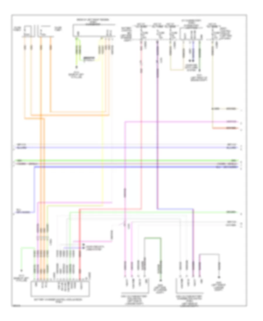
1.6L Turbo, Engine Performance Wiring Diagram, A/T (2 of 6) for Ford Fusion S 2013
List of elements for 1.6L Turbo, Engine Performance Wiring Diagram, A/T (2 of 6) for Ford Fusion S 2013:
- (engine controls sensor harness, near breakout to coil on plug 3)
- (engine controls sensor harness, near breakout to pcm)
- (engine controls sensor harness, near breakout to pcm) s134
- (instrument panel wiring harness, near breakout to g202)
- (right front of engine compt) air conditioning (a/c) pressure transducer
- (right front of engine compt) turbocharger boost pressure/charge air cooler temperature (tcbp/cact) sensor
- (top of engine) fuel pressure sensor
- (top of fuel tank) fuel level sensor
- (top of fuel tank) fuel tank pressure (ftp) sensor
- Accelerator pedal position (app) sensor (left side of dash)
- C1010
- C145
- C146
- C1558a
- C315
- Cact
- G101 (left front of engine compt)
- Generator
- Intake air temperature (iat) sensor (left front of engine compt)
- Nca
- Pnk
- S119 (engine controls sensor harness, near breakout to anti- lock brake system module)
- S131 (engine controls sensor harness, near breakout to pcm)
- S133
- S204
- S205 (main wiring harness, in breakout to steering column control module)
- S214
- S216
- Selector lever assembly (center console)
- Sigrtn
- Sst rtn
- Sst+
- Sst-
- Stop lamp switch (under left side of dash)
- Tcbp
- Vref
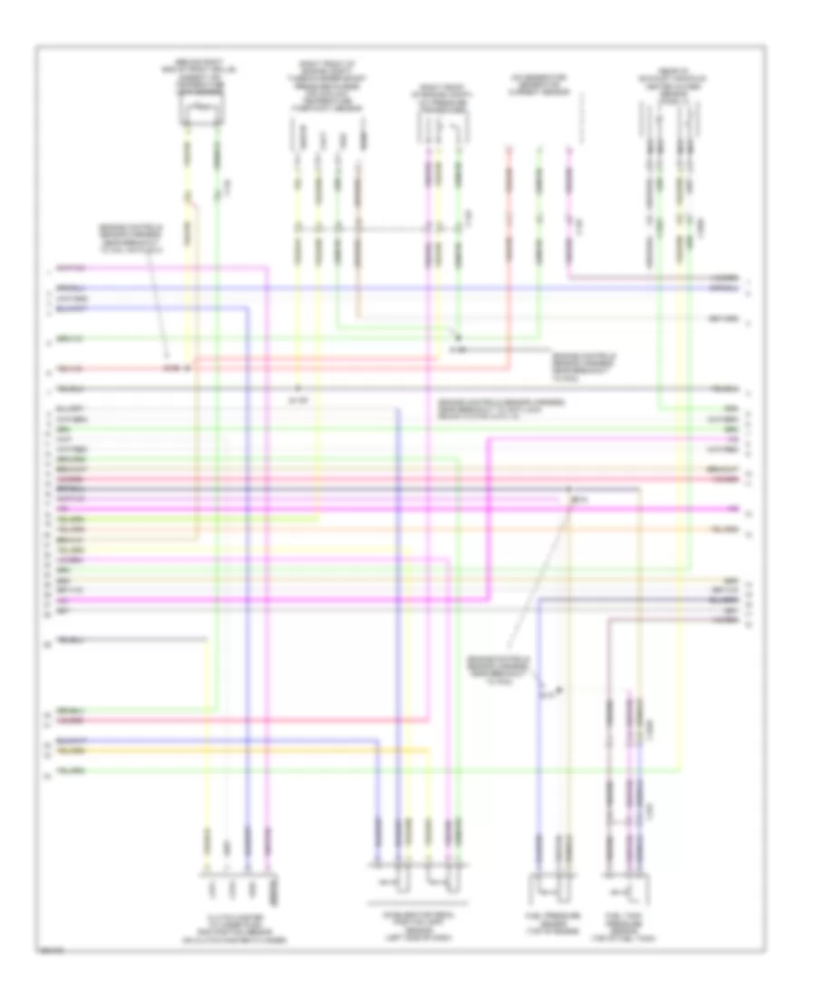
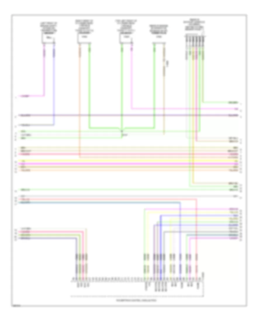
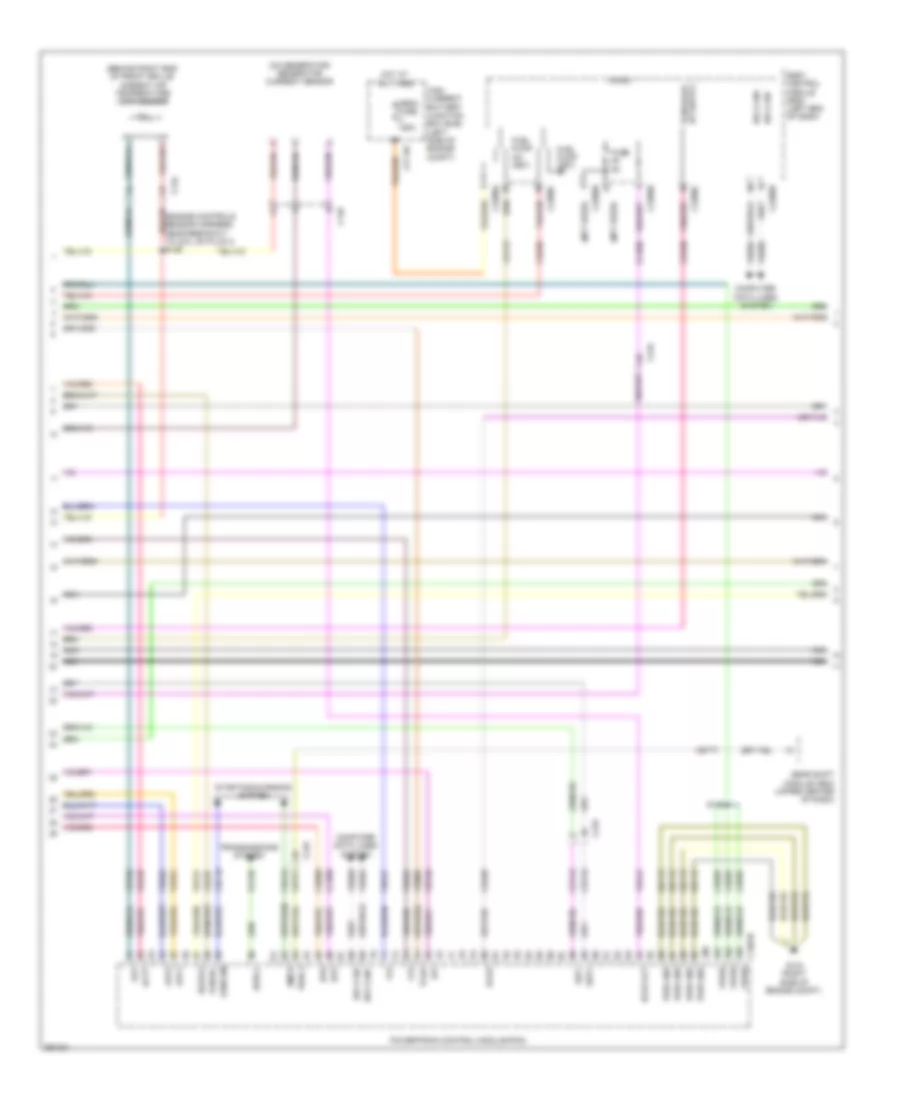
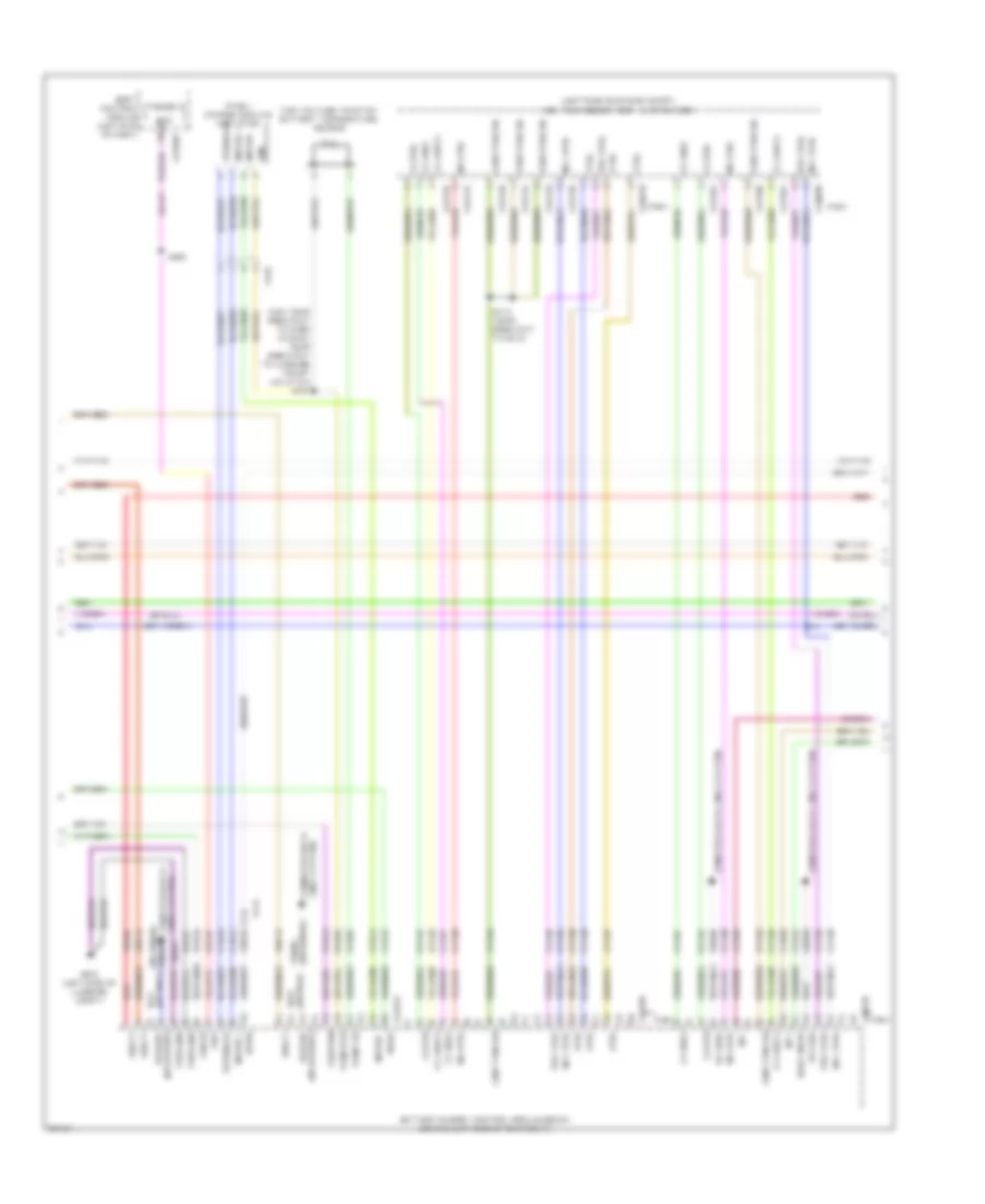
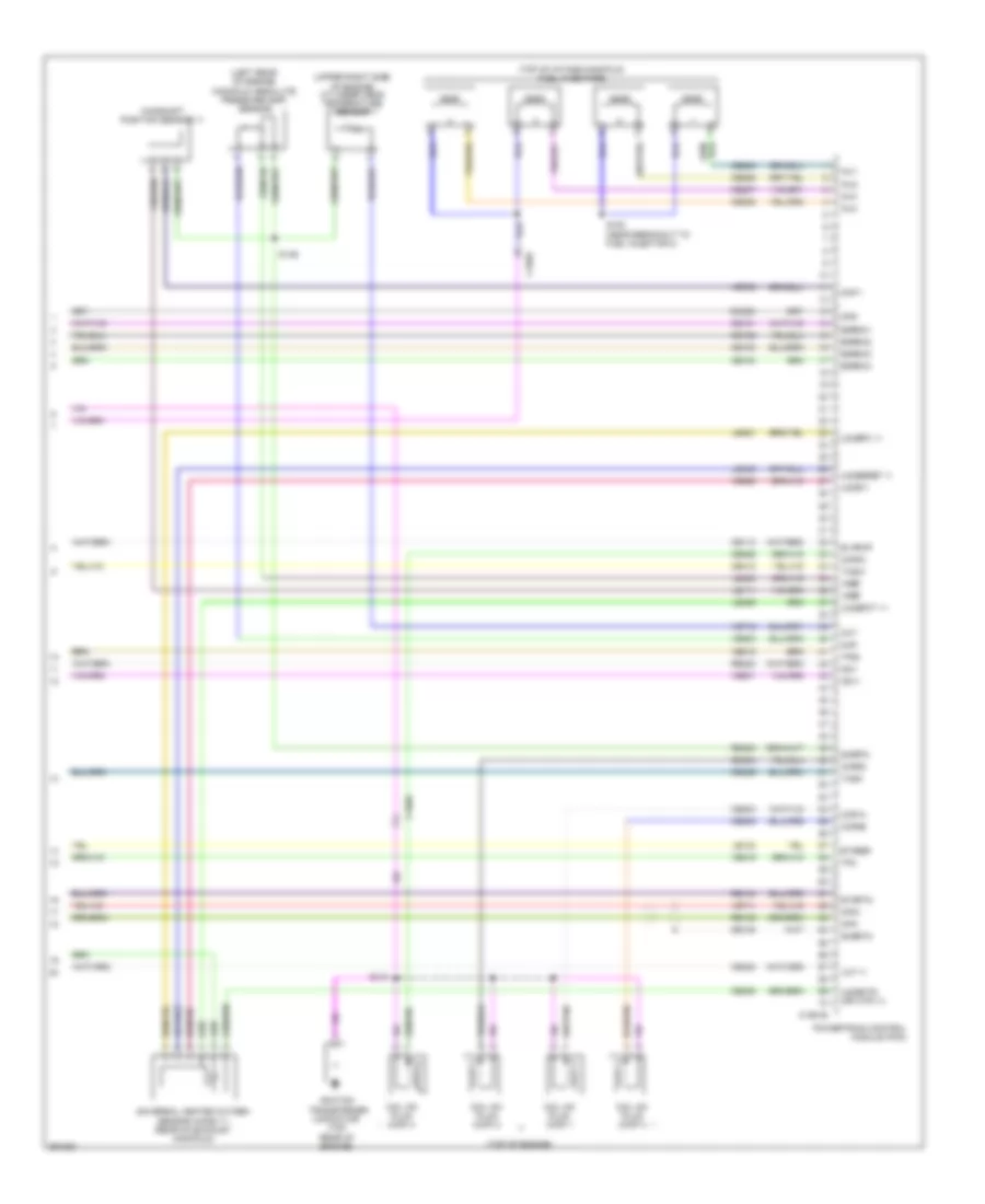
1.6L Turbo, Engine Performance Wiring Diagram, A/T (3 of 6) for Ford Fusion S 2013
List of elements for 1.6L Turbo, Engine Performance Wiring Diagram, A/T (3 of 6) for Ford Fusion S 2013:
- (behind right end of front grille) ambient air temperature (aat) sensor
- (engine controls sensor harness, near breakout to coil on plug 3) s126
- (engine controls sensor harness, near breakout to g101) s112
- (not used)
- (on generator) generator current sensor
- Aat
- Acpt
- App1
- App2
- Bcs2 alt
- Body control module (bcm) (left end of dash)
- Bpp
- Bps
- C1232b
- C134
- C146
- C1617f
- C219
- C2280a
- C2280b
- C2280c
- C2280h
- Cbb07
- Ccb08
- Cdc10
- Cdc54
- Ce237
- Ce420
- Ce436
- Ces09
- Cet42
- Cet43
- Computer data lines system
- Evap
- Frd
- Ftp
- Fuel pump (fet)
- Fuel pump on (fet)
- Fuse 5a
- G104 (right side of engine compt)
- Gd113
- Gencom
- High current battery junction box (bjb) (left side of engine compt)
- Ho2s12
- Hot at all times
- Hs1 can+
- Hs1 can-
- Iat
- Mega fuse 125a
- Micro
- Pcm rc
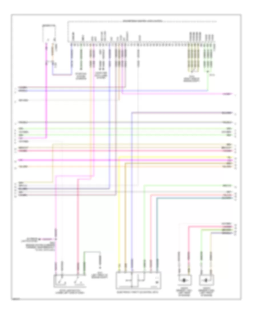
- Powertrain control module (pcm)
- Pwr gnd
- Smcs
- Sst+
- Sst-
- Starting/ charging system
- Tcbp
- Vdb04
- Vdb05
- Vdc61
- Ve701
- Ve702
- Ve727
- Ve731
- Ve740
- Ve750
- Ve805
- Ve922
- Vh433
- Vpwr
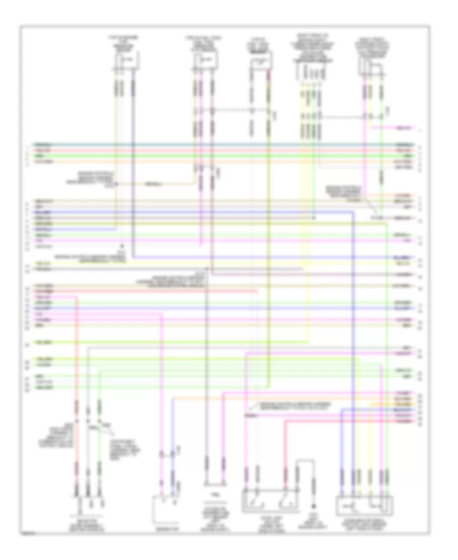
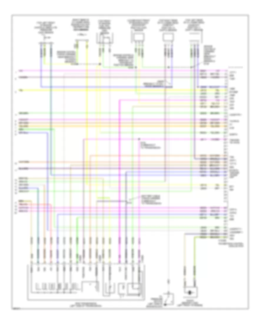
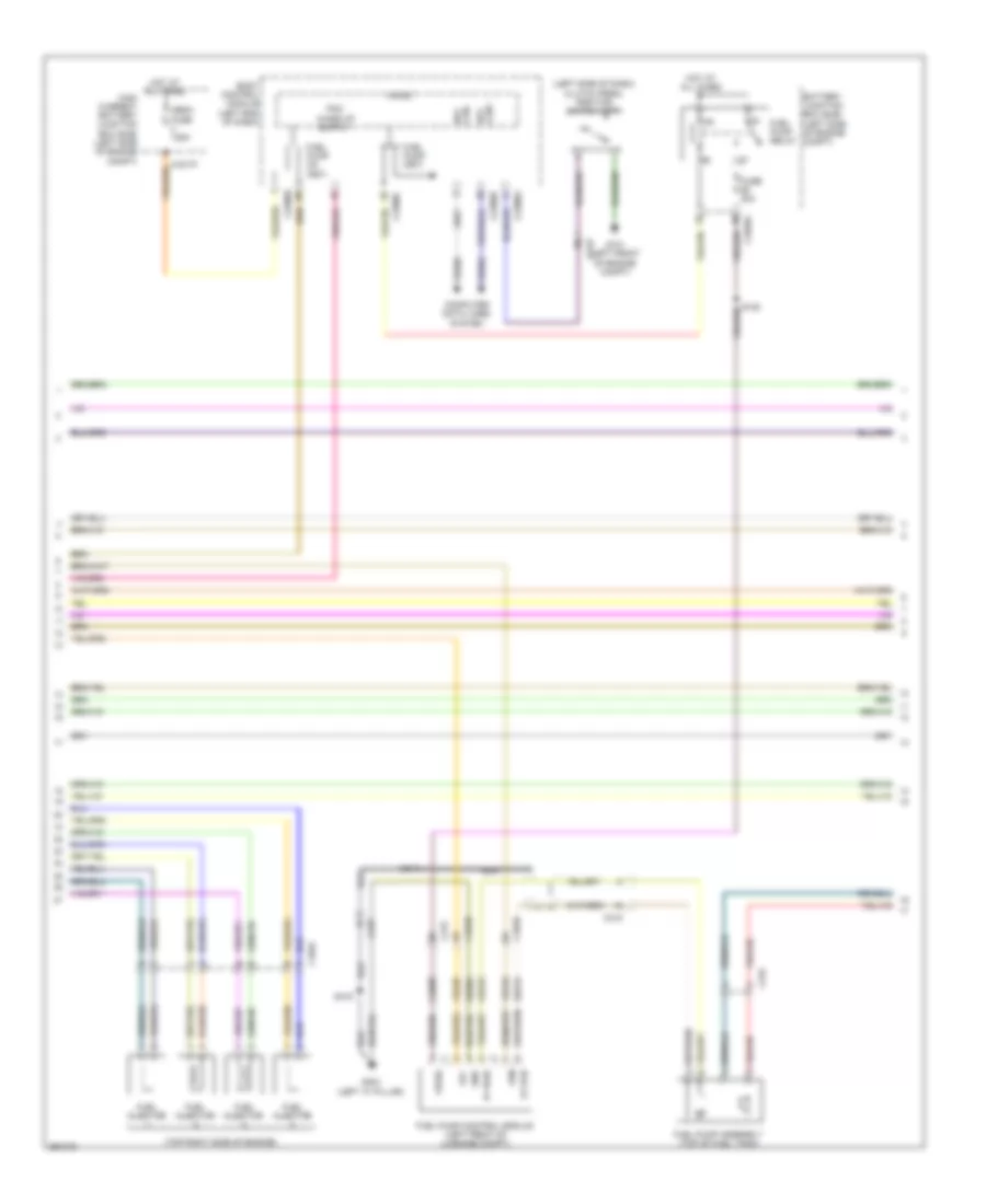
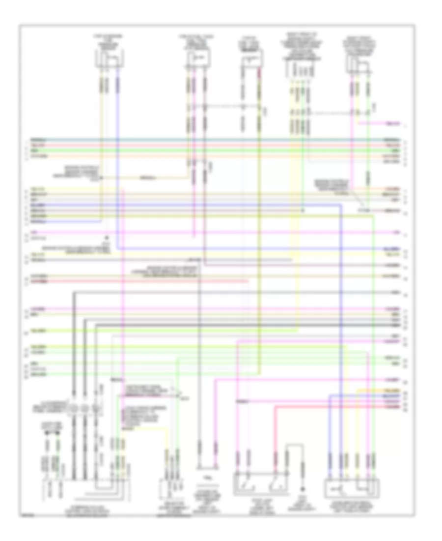
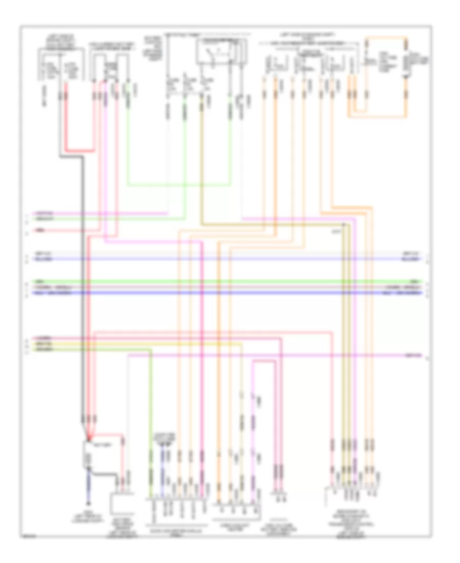
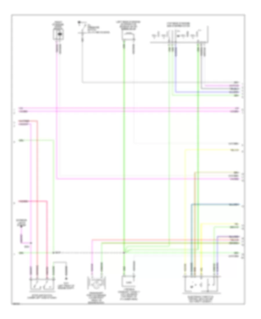
1.6L Turbo, Engine Performance Wiring Diagram, A/T (4 of 6) for Ford Fusion S 2013
List of elements for 1.6L Turbo, Engine Performance Wiring Diagram, A/T (4 of 6) for Ford Fusion S 2013:
- (engine controls wiring
- (rear of engine) evaporative emission (evap) purge valve
- (rear of exhaust manifold) heated oxygen sensor (ho2s) 12
- (rear of exhaust manifold) universal heated oxygen sensor (ho2s) 11
- (right front of cylinder head) variable camshaft timing 12 (vct12) solenoid
- (top left front of cylinder head) variable camshaft timing 11 (vct11) solenoid
- (top right side of engine) fuel injection pump
- (under right rear of vehicle) evap canister vent valve
- Atfpc
- Atfpm
- C1010
- C1026
- C1232e
- Ce205
- Ce206
- Ce207
- Ce208
- Ce226
- Ce304
- Ce305
- Ce412
- Ce426
- Cet05
- Cet07
- Cet09
- Cet49
- Cmp12
- Cop2d
- Cop3b
- Electronic throttle control (etc)
- Evap purge valve
- Fvr
- Fvrrtn
- Harness, near breakout to knock sensor 2) s147
- Inj1
- Inj1rtn
- Inj2
- Inj2rtn
- Inj3
- Inj3rtn
- Inj4
- Inj4rtn
- Ks1+
- Ks1-
- Le451
- Lpc
- Nca
- Powertrain control module (pcm)
- Re205
- Re206
- Re207
- Re208
- Re226
- Re323
- Re405
- S113
- S315
- Sigrtn
- Ssa
- Ssc
- Tacm+
- Tacm-
- Tft
- Tp1
- Tp2
- Tspc
- Uo2s11
- Uo2spc11
- Ve707
- Ve801
- Ve818
- Ve819
- Ve826
- Vet27
- Vyt11
- Vyt12
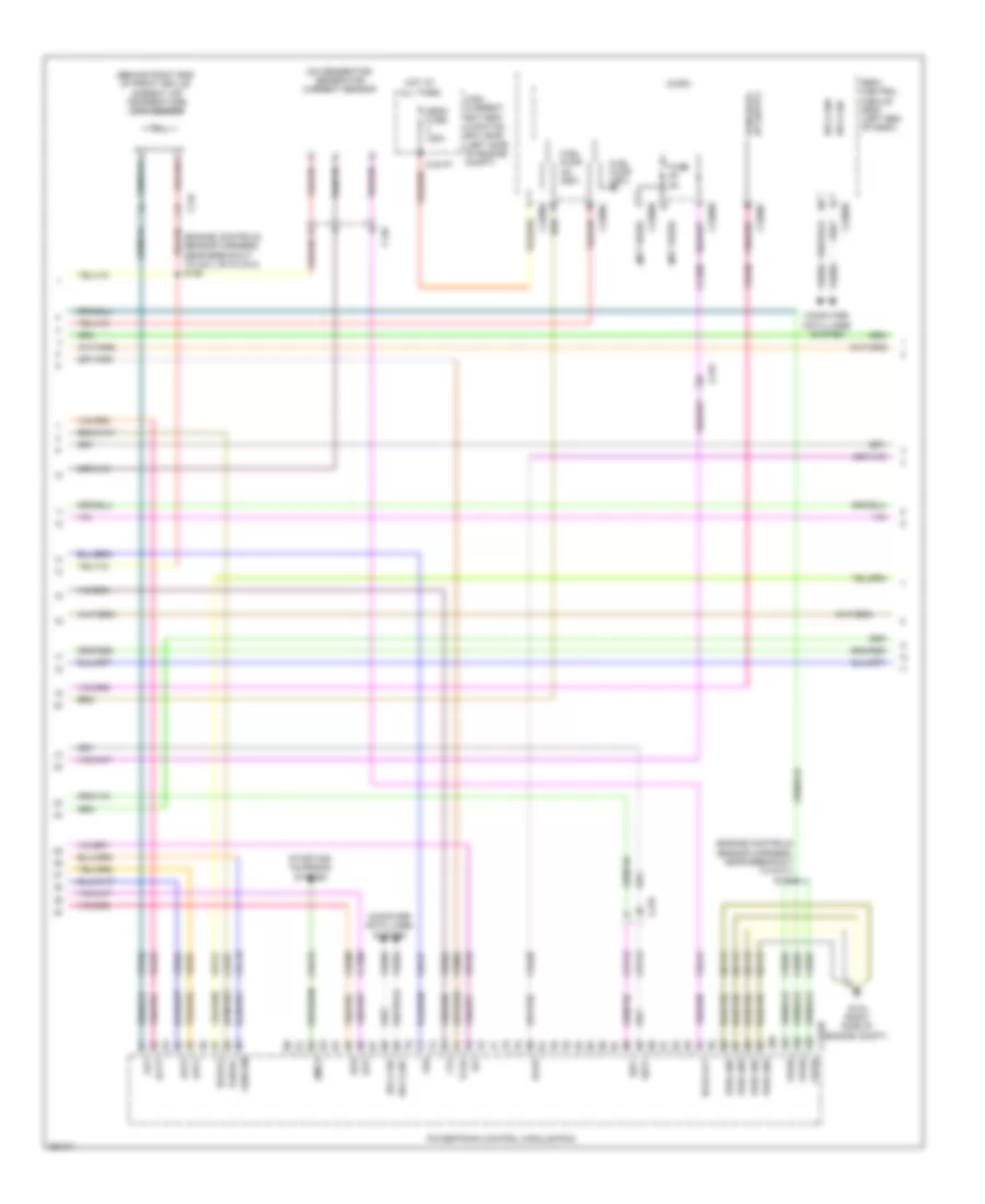
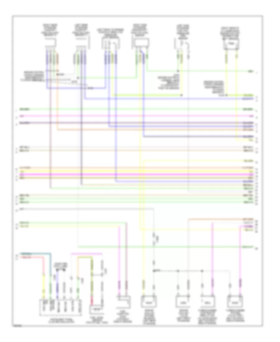
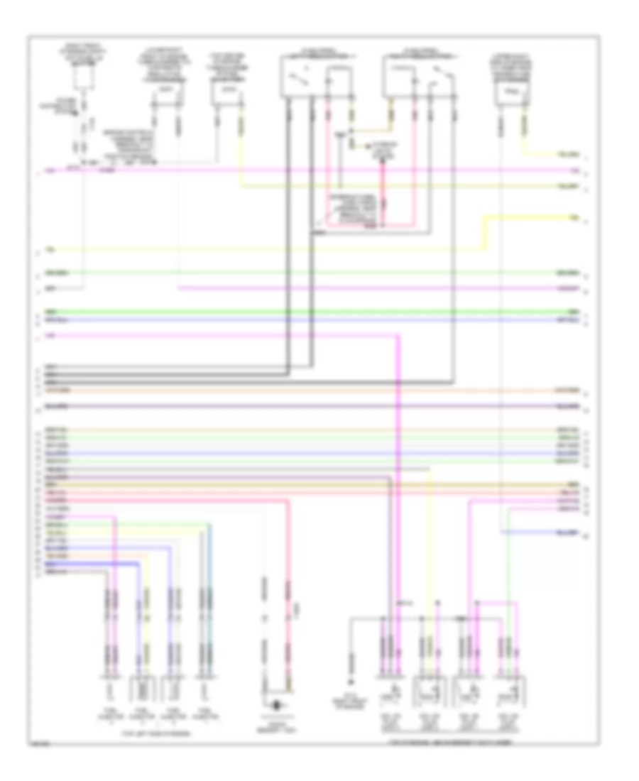
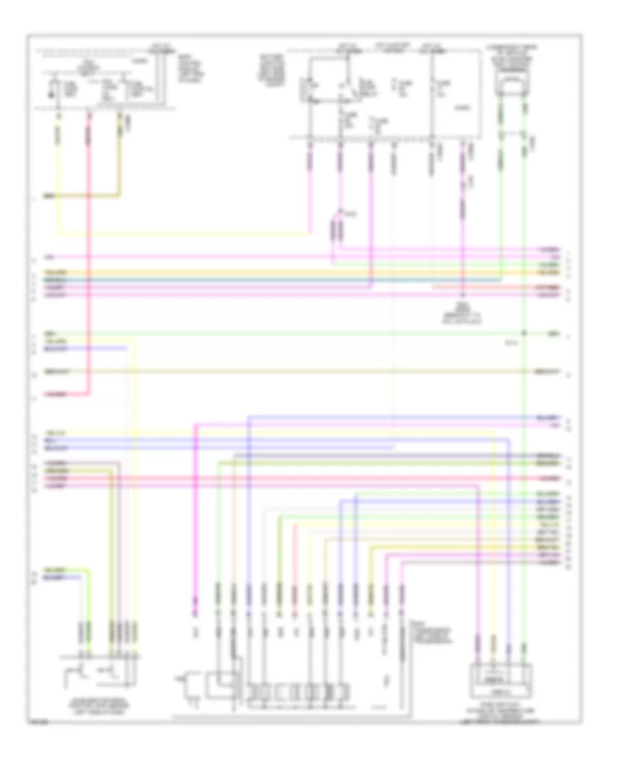
1.6L Turbo, Engine Performance Wiring Diagram, A/T (5 of 6) for Ford Fusion S 2013
List of elements for 1.6L Turbo, Engine Performance Wiring Diagram, A/T (5 of 6) for Ford Fusion S 2013:
- (bottom
- (bottom right front of engine) turbocharger (tc) wastegate regulating valve solenoid
- (engine controls harness, near breakout to crankshaft position sensor) s151
- (left front of engine) engine coolant valve
- (left rear of engine) engine cooling bypass solenoid
- (left side of engine compt) transmission fluid pump
- (right front of engine compt) active grille shutter
- (top of engine, above respective cylinder)
- (top right side of engine)
- Batt
- C1026
- C1045
- C134
- C146
- Coil on plug (cop) 1
- Coil on plug (cop) 2
- Coil on plug (cop) 3
- Coil on plug (cop) 4
- Fuel injector
- G101 (left front of engine compt)
- G110 (left rear of engine)
- Gnd
- Knock sensor 1 (ks1) (left rear of engine)
- Power distribution system
- Pwr/diag
- Right side of engine) turbocharger bypass valve (tcby)
- Run/start
- S110
- S139
- S144
- S148
- Spd command
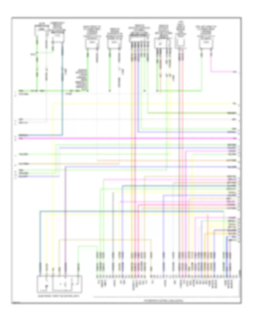
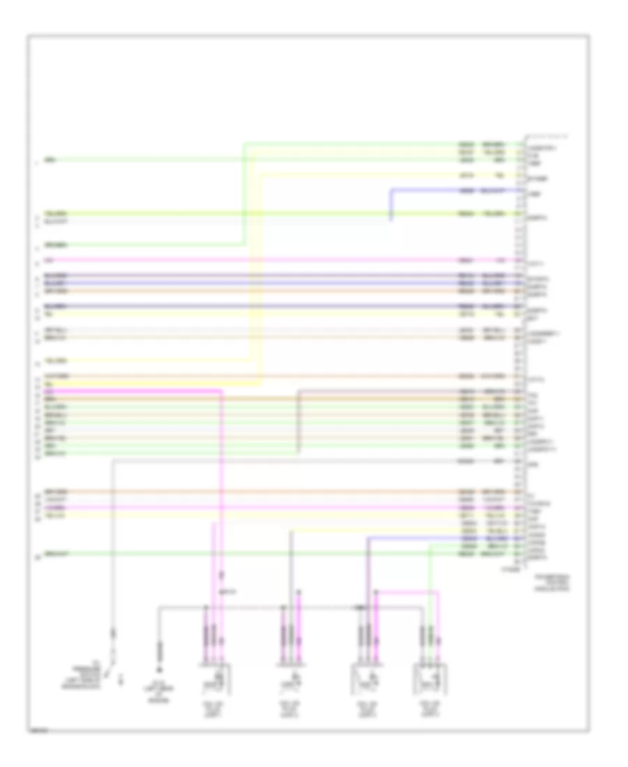
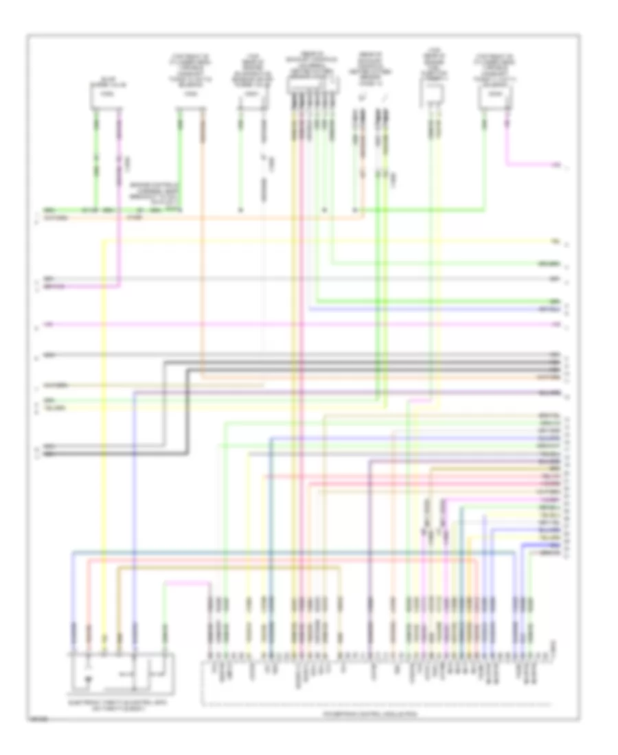
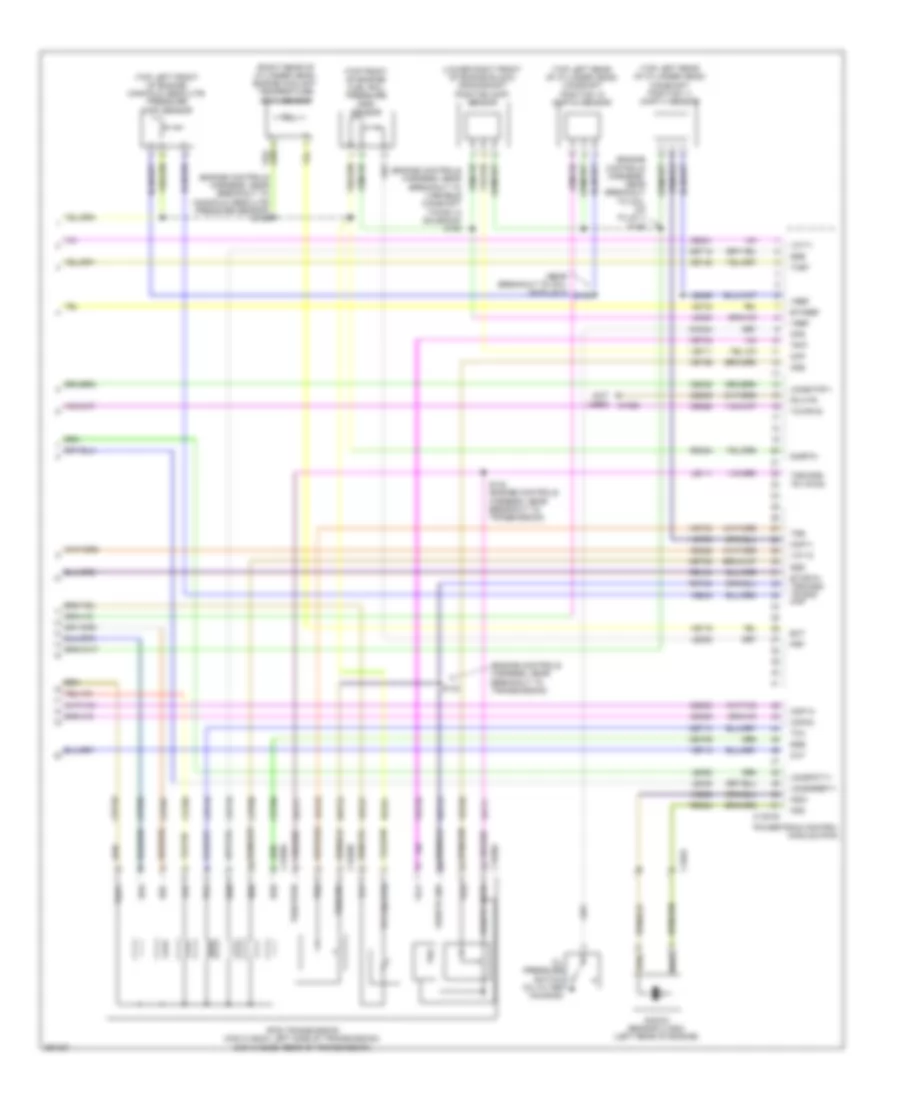
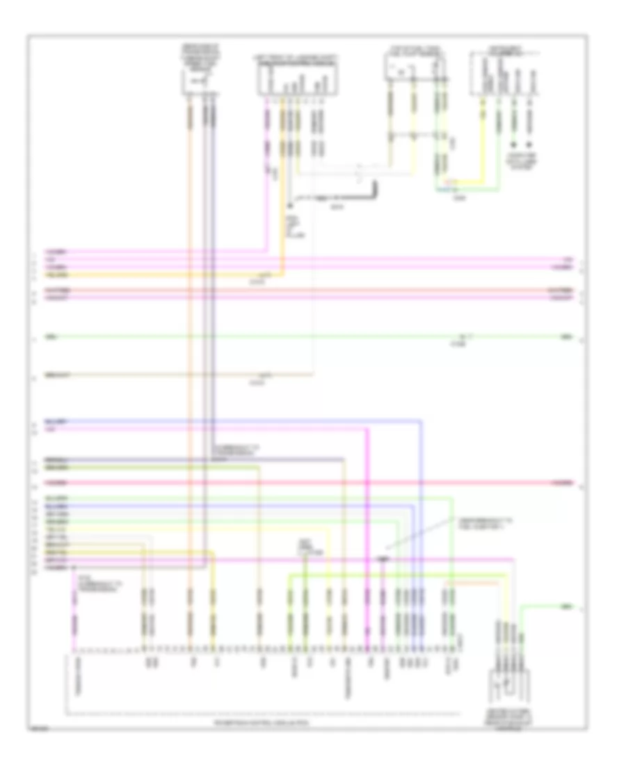
1.6L Turbo, Engine Performance Wiring Diagram, A/T (6 of 6) for Ford Fusion S 2013
List of elements for 1.6L Turbo, Engine Performance Wiring Diagram, A/T (6 of 6) for Ford Fusion S 2013:
- (battery cable wiring harness, in breakout to transmission)
- (engine control wiring harness, near breakout to knock sensor 2) s149
- (engine controls harness, near breakout knock sensor 2) s146
- (engine controls harness, near breakout to crankshaft position sensor) s150
- (lower right front of engine block) crankshaft position (ckp) sensor
- (near breakout to coil knock sensor 2) s145
- (right rear of cylinder head) engine coolant temperature (ect) sensor
- (top front of engine) fuel rail pressure (frp) sensor
- (top left front of engine) manifold absolute pressure (map) sensor
- (top left rear of cylinder head) camshaft position 11 (cmp11) sensor
- (top right rear of cylinder head) camshaft position 12 (cmp12) sensor
- 6f35 transmission (left side of transmission)
- C1232e
- C1520a
- C1520b
- Ce166
- Ce167
- Ce235
- Ce303
- Ce306
- Ce421
- Ce422
- Ce460
- Cet05
- Cet06
- Cet07
- Cet08
- Cet09
- Cet10
- Cet18
- Cet49
- Ckp
- Cmc24
- Cmp11
- Cop1a
- Cop4c
- Cvb
- Ect
- Etcref
- Etcrtn tss/oss/ tr gnd map
- Frp
- Knock sensor 2 (ks2) (left front of engine)
- Ks2+
- Ks2-
- Le111
- Le134
- Le238
- Le423
- Le448
- Le452
- Le458
- Lpc
- Oil pressure switch (left side of engine block)
- Ops
- Oss
- Oss/tr gnd
- Oss/tr vpwr
- Powertrain control module (pcm)
- Re134
- Re324
- Re454
- Ret24
- S142 (in breakout to transmission)
- S143
- Sigrtn
- Ssa
- Ssb
- Ssc
- Ssd
- Sse
- Tcby
- Tcc
- Tcwrvs
- Tft
- Tft sig rtn
- Tr-p
- Trs
- Tspc
- Tss
- Tss/gnd
- Tss/oss/ tr vpwr
- Tss/vpwr
- Uo2sgref11
- Uo2shtr11
- Uo2spct11
- Vct11
- Vct12
- Ve706
- Ve711
- Ve716
- Ve802
- Ve803
- Ve836
- Vet26
- Vet27
- Vet32
- Vet33
- Vref
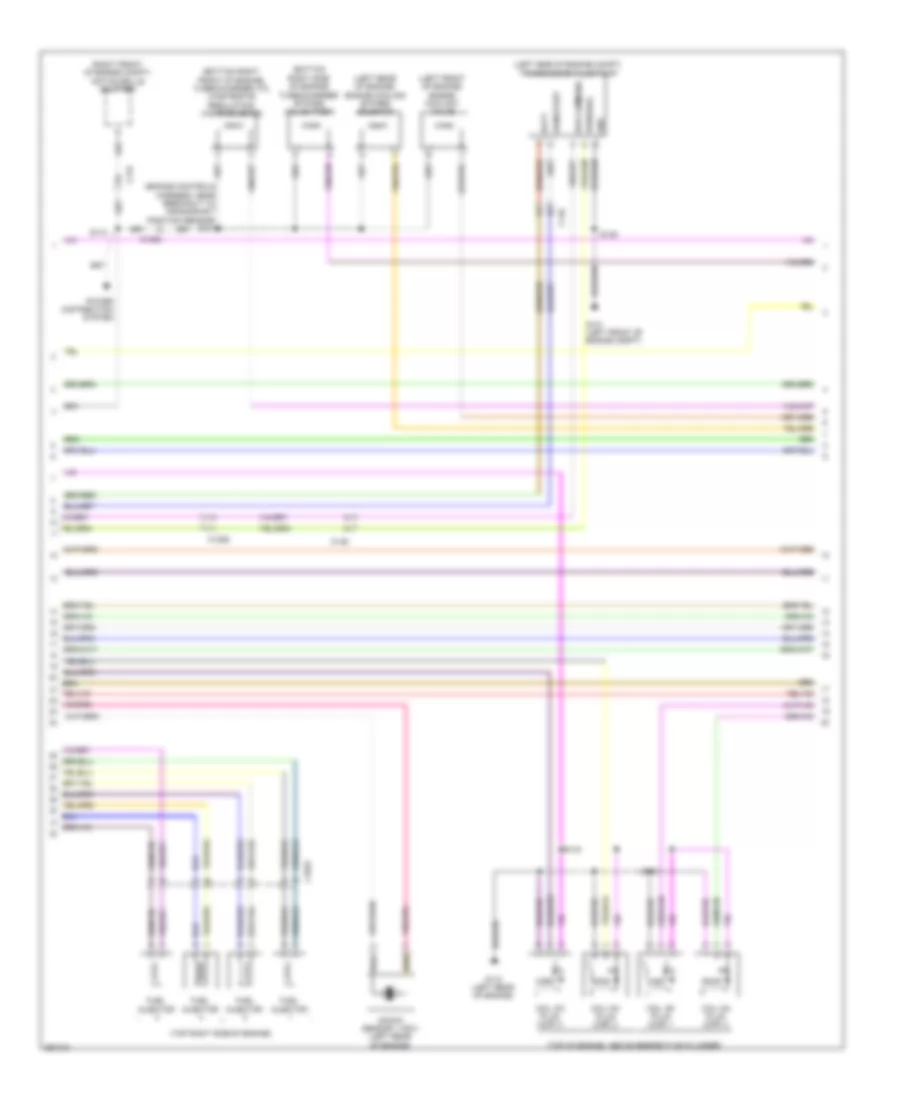
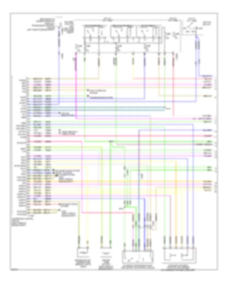
1.6L Turbo, Engine Performance Wiring Diagram, M/T (1 of 7) for Ford Fusion S 2013
List of elements for 1.6L Turbo, Engine Performance Wiring Diagram, M/T (1 of 7) for Ford Fusion S 2013:
- Aat
- Accr
- Acpt
- Air conditioning
- Air conditioning system
- App1
- App2
- Apprtn 1
- Apprtn 2
- Appvref1
- Appvref2
- Battery junction box (bjb) (left side of engine compt)
- C1010
- C1026
- C1035a
- C1232b
- Cact
- Canv
- Cbb26
- Cdc12
- Cdc15
- Cdc35
- Ce113
- Ce114
- Ce170
- Ce233
- Ce237
- Ce436
- Cec01
- Cec02
- Cet47
- Ch302
- Ch307
- Computer data lines system
- Cooling fans system
- Cpc
- Cpp1
- Cpp2
- Cr115
- Dc to dc converter control module (w/ auto start/ stop system (right rear of engine compt)
- Evap canister vent valve (under right rear of vehicle)
- Evap purge valve
- Evapcp
- Exterior lights system
- Fpc
- Fpm
- Fuse 10a
- Fuse 15a
- Fuse 20a
- Genmon
- Hfc
- Ho2s12
- Hot at all times
- Hot in run or start
- Hsi can +
- Hsi can -
- Htr12
- Ies
- Ispr
- Le136
- Le137
- Le230
- Le423
- Le424
- Le456
- Le458
- Lfc
- Lin
- Pcm power relay
- Pcm rc
- Pcm-wake
- Powertrain control module (pcm)
- Re136
- Re137
- Re230
- Re242
- Re332
- Re335
- Re403
- Re407
- S110
- S113
- S315
- Sigrtn
- Smc
- Sme
- Smr
- Starting/charging system
- System
- Vacc
- Vdb04
- Vdb05
- Vdn06
- Ve225
- Ve462
- Ve518
- Ve701
- Ve702
- Ve731
- Ve750
- Ve757
- Vh433
- Vref
1.6L Turbo, Engine Performance Wiring Diagram, M/T (2 of 7) for Ford Fusion S 2013
List of elements for 1.6L Turbo, Engine Performance Wiring Diagram, M/T (2 of 7) for Ford Fusion S 2013:
- (behind right end of front grille) ambient air temperature (aat) sensor
- (engine controls sensor harness, near breakout to anti-lock brake system module)
- (engine controls sensor harness, near breakout to coil on plug 3)
- (engine controls sensor harness, near breakout to pcm)
- (on generator) generator current sensor
- (rear of exhaust manifold) heated oxygen sensor (ho2s) 12
- (right front of engine compt) a/c pressure transducer
- (right front of engine compt) turbocharger boost pressure/charge air coolant temperature (tcbp/cact) sensor
- Accelerator pedal position (app) sensor (left side of dash)
- C1010
- C1026
- C134
- C145
- C146
- C315
- Cact
- Clutch master cylinder push rod position sensor (on clutch master cylinder)
- Cpp1
- Cpp2
- Fuel pressure sensor (top of engine)
- Fuel tank pressure sensor (top of fuel tank)
- Nca
- S119
- S126
- S131
- S133
- S134
- Sigrtn
- Tcbp
- Vref
1.6L Turbo, Engine Performance Wiring Diagram, M/T (3 of 7) for Ford Fusion S 2013
List of elements for 1.6L Turbo, Engine Performance Wiring Diagram, M/T (3 of 7) for Ford Fusion S 2013:
- Bcs2alt
- Bpp
- Bps
- C1232b
- C146
- C1558a
- Cbb07
- Ccb08
- Cdc10
- Cdc54
- Ce420
- Ces09
- Computer data lines system
- Electronic throttle control (etc)
- Evap
- Exterior lights system
- Frp
- Ftp
- G101 (left front of engine compt)
- G104 (right side of engine compt)
- Gd113
- Gencom
- Generator
- Hs1 can +
- Hs1 can -
- Iat
- Knock sensor 1 (ks1) (left rear of engine)
- Knock sensor 2 (ks2) (left front of engine)
- Powertrain control module (pcm)
- Pwrgnd
- S112
- S204 (engine controls sensor harness, near breakout to coil on plug 3)
- Smcs
- Starting/ system charging
- Stop lamp switch (under left side of dash)
- Tcbp
- Vdb04
- Vdb05
- Vdc61
- Ve727
- Ve740
- Ve805
- Ve922
- Vpwr
1.6L Turbo, Engine Performance Wiring Diagram, M/T (4 of 7) for Ford Fusion S 2013
List of elements for 1.6L Turbo, Engine Performance Wiring Diagram, M/T (4 of 7) for Ford Fusion S 2013:
- (left front of engine compt) intake air temperature sensor
- (rear of engine) evaporative emission (evap) purge valve
- (rear of exhaust manifold) universal heated oxygen sensor (ho2s) 11
- (right front of cylinder head) variable camshaft timing 12 (vct12) solenoid
- (top left front of cylinder head) variable camshaft timing 11 (vct11) solenoid
- C1026
- C1232e
- Ce205
- Ce206
- Ce207
- Ce208
- Ce226
- Ce412
- Ce426
- Fvr
- Fvrrtn
- Inj1
- Inj1 rtn
- Inj2
- Inj2 rtn
- Inj3
- Inj3 rtn
- Inj4
- Inj4 rtn
- Ks1+
- Ks1-
- Ks2+
- Ks2-
- Nca
- Powertrain control module (pcm)
- Re205
- Re206
- Re207
- Re208
- Re226
- Re323
- Re324
- S147
- Tacm+
- Tacm-
- Ve801
- Ve802
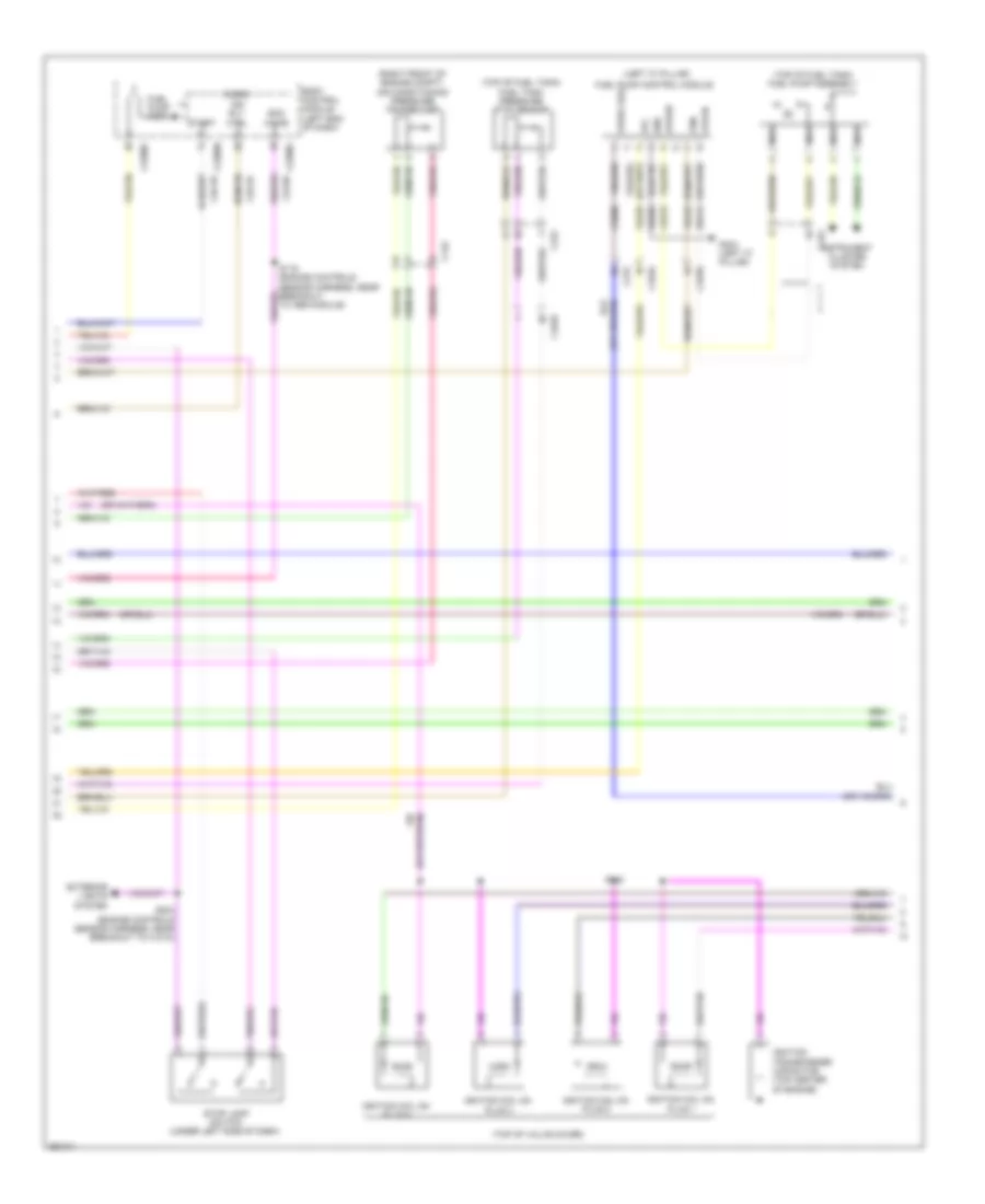
1.6L Turbo, Engine Performance Wiring Diagram, M/T (5 of 7) for Ford Fusion S 2013
List of elements for 1.6L Turbo, Engine Performance Wiring Diagram, M/T (5 of 7) for Ford Fusion S 2013:
- (left side of dash) clutch pedal position switch (cpp)
- (top right side of engine)
- Battery junction box (bjb) (left side of engine compt)
- Body control module (left end of dash)
- C1010
- C1035a
- C1045
- C1617f
- C215
- C219
- C2280a
- C2280b
- C2280c
- C2280g
- C315
- Can - hs1
- Ce515
- Ce608
- Computer data lines system
- Fp pwr
- Fp rtn
- Fpc
- Fpm
- Fuel injector
- Fuel pump (fet)
- Fuel pump assembly (top of fuel tank)
- Fuel pump control module (left front of luggage compt)
- Fuel pump on (fet)
- Fuel pump relay
- Fuse 30a
- G101 (left front of engine compt)
- G304 (left "c" pillar)
- Gd304
- Gnd
- High current battery junction box (bjb) (left side of engine compt)
- Hot at all times
- Hs1 can +
- Mega fuse 125a
- Micro
- Nca
- Re515
- S120
- S415
- S419
- Vdb04
- Vdb05
- Ve225
- Ve518
- Vpwr
1.6L Turbo, Engine Performance Wiring Diagram, M/T (6 of 7) for Ford Fusion S 2013
List of elements for 1.6L Turbo, Engine Performance Wiring Diagram, M/T (6 of 7) for Ford Fusion S 2013:
- (engine control wiring harness, near breakout to knock sensor 2)
- (left front of engine) manifold absolute pressure (map) sensor
- (left rear of engine) camshaft position (cmp) sensor 11
- (left side of engine) fuel rail pressure (frp) sensor
- (right rear of cylinder head) engine coolant temperature (ect) sensor
- (right rear of engine) camshaft position (cmp) sensor 12
- (right side of engine) crankshaft position (ckp) sensor
- C1026
- C248
- C315
- Computer data lines system
- Engine coolant valve (left front of engine)
- Engine cooling bypass solenoid (left rear of engine)
- Fuel injection pump (top right side of engine)
- Fuel level sensor (top of fuel tank)
- Fuel lvl 2
- Fuel rtn
- Fuel snd
- Instrument panel cluster module (ipc)
- Ms3 can +
- Ms3 can -
- Pnk
- Return
- S145
- S146
- S149
- S150 (engine controls harness, near breakout to crankshaft position sensor)
- S151
- S152
- Sig
- Turbocharger bypass valve (tcby) (bottom right side of engine)
- Turbocharger wastegate regulating valve solenoid (bottom right side of engine)
1.6L Turbo, Engine Performance Wiring Diagram, M/T (7 of 7) for Ford Fusion S 2013
List of elements for 1.6L Turbo, Engine Performance Wiring Diagram, M/T (7 of 7) for Ford Fusion S 2013:
- C1232e
- Ce166
- Ce167
- Ce235
- Ce303
- Ce304
- Ce305
- Ce306
- Ce421
- Ce422
- Ce460
- Ckp
- Cmc24
- Cmp11
- Cmp12
- Coil on plug (cop) 1
- Coil on plug (cop) 2
- Coil on plug (cop) 3
- Coil on plug (cop) 4
- Cop1a
- Cop2d
- Cop3b
- Cop4c
- Cvb
- Ect
- Etcref
- Etcrtn
- Frp
- G110 (left rear of engine)
- Le134
- Le238
- Le423
- Le448
- Le451
- Le452
- Le458
- Map
- Oil pressure switch (left side of engine block)
- Ops
- Powertrain control module (pcm)
- Re134
- Re238
- Re405
- Re429
- Re433
- Re454
- S144
- S148
- Sigrtn
- Tcby
- Tcwrvs
- Tp1
- Tp2
- Uo2s11
- Uo2sgref11
- Uo2shtr11
- Uo2spc11
- Uo2spct11
- Vct11
- Vct12
- Ve706
- Ve707
- Ve711
- Ve716
- Ve803
- Ve818
- Ve819
- Ve826
- Ve836
- Vref
2.0L FLEX FUEL
2.0L Flex Fuel, Engine Performance Wiring Diagram (1 of 6) for Ford Fusion S 2013
List of elements for 2.0L Flex Fuel, Engine Performance Wiring Diagram (1 of 6) for Ford Fusion S 2013:
- (engine controls sensor harness, near breakout to anti-lock brake system module) s120
- 10a
- Accr
- Air conditioning system
- Apprtn1
- Apprtn2
- Appvref1
- Appvref2
- Awd-m
- Battery junction box (bjb) (left side of engine compt)
- C1010
- C1026
- C1035a
- C1381b
- C215
- C219
- C248
- C315
- Cact
- Cbb26
- Cdc12
- Cdc15
- Cdc35
- Ce113
- Ce233
- Ce436
- Ce515
- Ce608
- Cec01
- Cec02
- Ch302
- Computer data lines system
- Cooling fans system
- Cr115
- Evapcp
- Fp pwr
- Fp rtn
- Fpc
- Fpm
- Fuel lvl2
- Fuel pump (fp) assembly (top of fuel tank)
- Fuel pump control module (left front of luggage compt)
- Fuel pump relay
- Fuel rtn
- Fuel sndr
- Fuse
- Fuse 10a
- Fuse 15a
- Fuse 20a
- Fuse 30a
- G304 (left "c" pillar)
- Gd304
- Genmon
- Gnd
- Hfc
- Hot at all times
- Hot in start or run
- Hs3 can +
- Hs3 can -
- Htr12
- Ies
- Instrument panel cluster (ipc) module
- Isp-r
- Le136
- Le137
- Le230
- Le423
- Le424
- Lfc
- Lin
- Nca
- Pcm power relay
- Pcm wake
- Powertrain control module (pcm)
- Re136
- Re137
- Re230
- Re242
- Re332
- Re406
- Re407
- Re515
- Return
- S415
- S419
- Sig
- Sigrtn
- Smc
- Smr
- Starting/ charging system
- Transmissions system
- Vacc
- Vcf34
- Vdn06
- Ve225
- Ve462
- Ve518
- Vpwr
- Vref
2.0L Flex Fuel, Engine Performance Wiring Diagram (2 of 6) for Ford Fusion S 2013
List of elements for 2.0L Flex Fuel, Engine Performance Wiring Diagram (2 of 6) for Ford Fusion S 2013:
- (engine controls sensor harness, near breakout to anti- lock brake system module)
- (engine controls sensor harness, near breakout to pcm)
- (engine controls sensor harness, near breakout to pcm) s134
- (instrument panel wiring harness, near breakout to g202)
- (right front of engine compt) air conditioning (a/c) pressure transducer
- (right front of engine compt) turbocharger boost pressure/charge air cooler temperature (tcbp/cact) sensor
- (top of engine) fuel pressure sensor
- (top of fuel tank) fuel level sensor
- (top of fuel tank) fuel tank pressure (ftp) sensor
- Accelerator pedal position (app) sensor (left side of dash)
- C1010
- C145
- C218b
- C218c
- C2414a
- C2414d
- C315
- Cact
- Cet42
- Cet43
- Clockspring (behind steering wheel assembly)
- Computer data lines system
- G101 (left front of engine compt)
- Hs2 can+
- Hs2 can-
- Intake air temperature (iat) sensor (left front of engine compt)
- Nca
- Nca sst rtn
- Nca sst+
- Pnk
- Re407
- S119
- S131 (engine controls sensor harness, near breakout to pcm)
- S133
- S204
- S205
- S214
- S216
- Selector lever assembly (fusion) (center console)
- Sigrtn
- Sst-
- Steering column control module (sccm) (on steering column)
- Stop lamp switch (under left side of dash)
- Tcbp
- Vdb25
- Vdb26
- Vref
2.0L Flex Fuel, Engine Performance Wiring Diagram (3 of 6) for Ford Fusion S 2013
List of elements for 2.0L Flex Fuel, Engine Performance Wiring Diagram (3 of 6) for Ford Fusion S 2013:
- (behind right end of front grille) ambient air temperature (aat) sensor
- (engine controls sensor harness, near breakout to coil on plug 3) s126
- (not used)
- (on generator) generator current sensor
- Aat
- Acpt
- App1
- App2
- Awd-c
- Bcs2 alt
- Body control module (bcm) (left end of dash)
- Bpp
- Bps
- C134
- C1381b
- C146
- C1716f
- C219
- C2280a
- C2280b
- C2280c
- C2280h
- Cbb07
- Ccb08
- Cdc10
- Cdc54
- Ce226
- Ce237
- Ce420
- Ce436
- Ces09
- Cet42
- Cet43
- Computer data lines system
- Cr115
- Evap
- Flp
- Ftp
- Fuel pump (fet)
- Fuel pump on (fet)
- Fuse 5a
- G104 (right side of engine compt)
- Gd113
- Gear shift module (gsm) (upper center of dash)
- Gencom
- High current battery junction box (bjb) (left side of engine compt)
- Ho2s12
- Hot at all times
- Hs1 can+
- Hs1 can-
- Iat
- Mega fuse 125a
- Micro
- Nca
- Pcm rc
- Powertrain control module (pcm)
- Pwr 2
- Pwr gnd
- S112
- Smcs
- Sst+
- Sst-
- Starting/charging system
- Tcbp
- Transmissions system
- Vcf35
- Vdb04
- Vdb05
- Vdc61
- Ve701
- Ve702
- Ve727
- Ve731
- Ve740
- Ve750
- Ve805
- Ve922
- Vet77
- Vh433
- Vpwr
2.0L Flex Fuel, Engine Performance Wiring Diagram (4 of 6) for Ford Fusion S 2013
List of elements for 2.0L Flex Fuel, Engine Performance Wiring Diagram (4 of 6) for Ford Fusion S 2013:
- (engine controls harness, near breakout to coil on plug 1) s147
- (not used)
- (not used) c1026
- (rear of exhaust manifold) heated oxygen sensor (ho2s) 12
- (rear of exhaust manifold) universal heated oxygen sensor (ho2s) 11
- (top front of cylinder head) variable camshaft timing 11 (vct11) solenoid
- (top front of cylinder head) variable camshaft timing 12 (vct12) solenoid
- (top rear of engine) evaporative emission (evap) purge valve
- (top rear of engine) fuel injection pump
- Atfpc
- Atfpm
- C1010
- C1026
- C1381e
- Ce205
- Ce206
- Ce207
- Ce208
- Ce226
- Ce304
- Ce305
- Ce412
- Ce426
- Cet05
- Cet07
- Cet09
- Cet49
- Cmp12
- Cop2d
- Cop3b
- Electronic throttle control (etc) (on throttle body)
- Evap purge valve
- Fvr
- Fvrrtn
- Inj1
- Inj1rtn
- Inj2
- Inj2rtn
- Inj3
- Inj3rtn
- Inj4
- Inj4rtn
- Ks1+
- Ks1-
- Le451
- Lpc
- Nca
- Powertrain control module (pcm)
- Re205
- Re206
- Re207
- Re208
- Re226
- Re323
- Re405
- S113
- Sigrtn
- Ssa
- Ssc
- Tacm+
- Tacm-
- Tft
- Tp1
- Tp2
- Tspc
- Uo2s11
- Uo2spc11
- Ve707
- Ve801
- Ve818
- Ve819
- Ve826
- Vet27
- Vyt11
- Vyt12
2.0L Flex Fuel, Engine Performance Wiring Diagram (5 of 6) for Ford Fusion S 2013
List of elements for 2.0L Flex Fuel, Engine Performance Wiring Diagram (5 of 6) for Ford Fusion S 2013:
- (engine controls harness, near breakout to crankshaft position sensor) s151
- (if equipped) left paddle shifter
- (if equipped) right paddle shifter
- (lower right front of engine) turbocharger (tc) wastegate regulating valve solenoid
- (right front of engine compt) active grille shutter
- (steering wheel horn wiring harness, near breakout to clockspring) s296
- (top center of engine) turbocharger bypass valve (tcby)
- (top left side of engine )
- (top of engine, above respective cylinder)
- (upper right side of engine) cylinder head temperature (cht) sensor
- C1026
- C1033
- C134
- Coil on plug (cop) 1
- Coil on plug (cop) 2
- Coil on plug (cop) 3
- Coil on plug (cop) 4
- Distribution system
- Fuel injector
- G110 (right front of engine)
- Interior lights system
- Knock sensor 1 (ks1)
- Nca
- Pnk
- S110
- S144
- S148
- S293
- S294
2.0L Flex Fuel, Engine Performance Wiring Diagram (6 of 6) for Ford Fusion S 2013
List of elements for 2.0L Flex Fuel, Engine Performance Wiring Diagram (6 of 6) for Ford Fusion S 2013:
- (engine controls harness, near breakout to coil on plug 1) s146
- (engine controls harness, near breakout to manifold absolute pressure sensor) s149
- (engine controls harness, near breakout to transmission)
- (engine controls harness, near breakout to variable camshaft timing 12 solenoid) s150
- (lower right front of engine block) crankshaft position (ckp) sensor
- (near breakout to coil on plug 4) s145
- (not used)
- (right rear of cylinder head) engine coolant temperature (ect) sensor
- (top front of engine) fuel rail pressure (frp) sensor
- (top left front of engine) manifold absolute pressure (map) sensor
- (top left rear of cylinder head) camshaft position 11 (cmp11) sensor
- (top left rear of cylinder head) camshaft position 12 (cmp12) sensor
- 6f35 transmission (con c1520a: left side of transmission) (con c1520b: rear of transmission)
- C1026
- C1033
- C1381e
- C1520a
- C1520b
- Ce148
- Ce235
- Ce239
- Ce303
- Ce306
- Ce421
- Ce422
- Ce460
- Cet05
- Cet06
- Cet07
- Cet08
- Cet09
- Cet10
- Cet18
- Cet49
- Cht
- Ckp
- Cmc24
- Cmp11
- Cop1a
- Cop4c
- Ect
- Etcref
- Etcrtn tss/oss/ tr gnd map
- Frp
- Knock sensor 2 (ks2) (left rear of engine)
- Ks2+
- Ks2-
- Le111
- Le134
- Le238
- Le423
- Le448
- Le452
- Le458
- Lpc
- Oil pressure switch (oil filter housing)
- Ops
- Oss
- Oss/tr gnd
- Oss/tr vpwr
- Pm htr
- Powertrain control module (pcm)
- Re134
- Re324
- Re454
- Ret24
- S142 (engine controls harness, near breakout to transmission)
- S143
- Sigrtn
- Ssa
- Ssb
- Ssc
- Ssd
- Sse
- Tcby
- Tcc
- Tcwrvs
- Tft
- Tft sig rtn
- Tr-p
- Trs
- Tspc
- Tss
- Tss/gnd
- Tss/oss/ tr vpwr
- Tss/vpwr
- Uo2sgref11
- Uo2shtr11
- Uo2spct11
- Vct11
- Vct12
- Ve706
- Ve711
- Ve712
- Ve716
- Ve802
- Ve803
- Vet26
- Vet27
- Vet32
- Vet33
- Vref
2.0L HYBRID
2.0L Hybrid, Engine Performance Wiring Diagram (1 of 9) for Ford Fusion S 2013
List of elements for 2.0L Hybrid, Engine Performance Wiring Diagram (1 of 9) for Ford Fusion S 2013:
- Aat
- Acc run
- Accelerator pedal position (app) sensor (on accelerator pedal bracket)
- Acpt
- Air conditioning system
- Air conditioning system trunk, tailgate, fuel doors system
- App1
- App2
- Apprtn1
- Apprtn2
- Appvref1
- Appvref2
- Battery junction box (left side of engine compt)
- Bpp
- Bps
- C1010
- C1026
- C1035a
- C1458a
- C175b
- C219
- Cbb07
- Cbb26
- Ccb08
- Cdc35
- Ce204
- Ce229
- Ce237
- Ce436
- Ces09
- Cet34
- Ch116
- Computer data lines system
- Cooling fans system
- Cto
- Ecby
- Ect2
- Engine coolant temperature sensor 2 (ect2) (phev)
- Evapldp
- Evapldppr
- Evaporative emission (evap) leak detection control module
- Fcv
- Ffdp
- Fpc
- Fpm
- Ftp
- Fuel pump (fp) relay
- Fuse 10a
- Fuse 15a
- Fuse 20a
- Fuse 30a
- G105 (right side of engine compt)
- Gd113
- Heater core shutoff (right rear of engine compt)
- Hot at all times
- Hs can+
- Hs can-
- Ignition relay
- Ignition switch
- Isp r
- Le136
- Le137
- Le230
- Le423
- Off
- Pcm power relay
- Pcmrc
- Powertrain control module (right rear of engine compt)
- Pwr gnd
- Pwr2
- Re136
- Re137
- Re141
- Re230
- Re259
- Re406
- Re407
- S112
- S113
- S315
- Secondary on board diagnostic module c/ transmission control module (left side of engine compt)
- Shift interlock system
- Sigrtn
- Start
- Tcs
- Transmissions system
- Vdb04
- Vdb05
- Ve203
- Ve225
- Ve518
- Ve701
- Ve702
- Ve716
- Ve750
- Ve922
- Ve934
- Vet76
- Vh433
- Vmc02
- Vpwr
- Vref
- Wake
2.0L Hybrid, Engine Performance Wiring Diagram (2 of 9) for Ford Fusion S 2013
List of elements for 2.0L Hybrid, Engine Performance Wiring Diagram (2 of 9) for Ford Fusion S 2013:
- (left "c" pillar)
- (right front of engine compt) air conditioning pressure transducer
- (top of fuel tank) fuel pump assembly
- (top of fuel tank) fuel tank pressure (ftp) sensor
- (top of valve cover)
- Body control module (left end of dash)
- C1010
- C145
- C215
- C2280c
- C2280h
- C315
- Cdc35
- Cdc55
- Ce436
- Ce515
- Ce608
- Ecm wake
- Exterior lights system
- Fpc
- Fpm
- Fppwr
- Fprtn
- Fuel pump (fet)
- Fuel pump control module
- G304 (left "c" pillar)
- Gd304
- Gnd
- Ign rly ctrl
- Ignition coil on plug 1
- Ignition coil on plug 2
- Ignition coil on plug 3
- Ignition coil on plug 4
- Ignition transformer capacitor (top center of engine)
- Instrument cluster system
- Micro
- Nca
- Re515
- S119 (engine controls sensor harness, near breakout to abs module)
- S144
- S204 (engine controls sensor harness, near breakout to c1010)
- Start
- Stop lamp switch (under left side of dash)
- Ve225
- Ve518
- Vpwr fuel
2.0L Hybrid, Engine Performance Wiring Diagram (3 of 9) for Ford Fusion S 2013
List of elements for 2.0L Hybrid, Engine Performance Wiring Diagram (3 of 9) for Ford Fusion S 2013:
- (left front of engine) knock sensor 1
- (left rear of engine) knock sensor 2
- (lower right front of engine block) crankshaft position sensor
- (phev) fuel tank isolation valve
- C1010
- C1026
- C146
- C175t
- Ce303
- Ce304
- Ce305
- Ckp
- Cop1a
- Cop2d
- Cop3b
- Cop4c
- Evaporative emission (evap) vapor blocking valve
- G105 (right side of engine compt)
- Gd113
- Gnd
- Hf35 transmission
- Ks 1+
- Ks 1-
- Ks 2+
- Ks 2-
- Le459
- Let57
- Powertrain control module (right rear of engine compt)
- Re135
- Re323
- Re324
- Ret57
- Sirtn
- Tr a1 sig
- Tr a2 sig
- Tr ref
- Tr rtn
- Ve711
- Ve801
- Ve802
- Vet56
- Vet57
- Vref
2.0L Hybrid, Engine Performance Wiring Diagram (4 of 9) for Ford Fusion S 2013
List of elements for 2.0L Hybrid, Engine Performance Wiring Diagram (4 of 9) for Ford Fusion S 2013:
- (at charge port) (phev) charge port light ring
- (rear of left front fender) (phev) charge port
- 40a
- Batt
- Battery charger control module (bccm) (phev)
- Battery junction box (left side of engine compt)
- Body control module (left end of dash)
- C1035a
- C1035b
- C1824
- C215
- C2280f
- C4455a
- C4455b
- Cbb29
- Computer data lines system
- Cyb55
- Cyb56
- Cyd14
- Fan fb
- Fan pwm
- Fuse 10a
- Fuse 15a
- Fuse 40a
- G101 (left front of engine compt)
- G113 (base of left "a" pillar)
- G400 (left side of luggage compt)
- Gnd
- High voltage battery charger cooling fan (phev) (left rear of luggage compt)
- High voltage battery cooling fan (left side of luggage compt)
- Hot at all times
- Hs can+
- Hs can-
- Hv (+)
- Hv (-)
- Hyb53
- Hyb54
- Inline fuse 1
- Inline fuse 2
- Red
- Resistor
- Ryb57
- S999
- Sbb57
- Vbatt
- Vdb04
- Vdb05
- Vpwr
- Vyb18
- Vyb19
- Wake
2.0L Hybrid, Engine Performance Wiring Diagram (5 of 9) for Ford Fusion S 2013
List of elements for 2.0L Hybrid, Engine Performance Wiring Diagram (5 of 9) for Ford Fusion S 2013:
- (left side of engine compt) high voltage battery junction box
- (mkz: near breakout to c495) (fusion: near breakout to luggage compt lid latch) s407
- (or hs/can+)
- (or hs/can-) hs/can+
- (or vdb04) vdb05
- (phev) charge cooling actuator
- Battery energy control module (becm) (behind left side of rear seat)
- Body control module (left end of dash)
- C215
- C2280d
- C4236b
- C4236c
- C4237a
- C4237b
- C4815b
- C4815c
- C4815d
- C4815e
- C4816b
- C495
- Cbb52
- Computer data lines system
- Cont pwr en
- Cr167
- Cs aout2
- Cs rtn
- Cs vref
- Ctrl
- Cyb03
- Cyb04
- Cyb10
- Cyb12
- Cyb13
- Cyc03
- Cyc04
- Cyc05
- Cyc06
- Cyc07
- Cyc08
- Cyc09
- Cyd14
- Dcdc wkup
- Ens
- Fan fb
- Fan pwm
- Feedback
- Fhev
- G400 (left side of luggage compt)
- Gd347
- Gnd
- High voltage traction battery temperature sensor
- Hs can+
- Hs can-
- Hs/can-
- Int+
- Int-
- Lines system computer data
- Lyc01
- Mc+ ctrl
- Mc-ctrl
- Micro
- Motor +
- Motor -
- Phev
- Prc ctrl
- Pwr gnd
- Red
- Ryb07
- Ryc01
- S235
- S415 (near breakout to c315)
- Sbf04
- Sbp14
- Temp rtn
- Temp sig
- Vbatt
- Vdb04
- Vdb04 (or vdb05)
- Vdb05
- Vpwr
- Vyb07
- Vyb18
- Vyb19
- Vyc02
- Wake
2.0L Hybrid, Engine Performance Wiring Diagram (6 of 9) for Ford Fusion S 2013
List of elements for 2.0L Hybrid, Engine Performance Wiring Diagram (6 of 9) for Ford Fusion S 2013:
- (left side of engine compt) (phev) high voltage battery junction box
- (left side of engine compt) dual battery fuse assembly
- (not used)
- 200a
- 30a
- Battery
- Battery junction box (left side of engine compt)
- Battery monitoring sensor (left rear of luggage compt)
- C1035b
- C1035c
- C1458a
- C1458e
- C1458g
- C1617a
- C1617e
- C1617k
- C1815a
- C1815b
- C4000
- C4001
- C4002
- C4453a
- C4453b
- C4453c
- C4453d
- C4815a
- C4815f
- C4815g
- C4815h
- Cabin coolant heater
- Cbb51
- Ce613
- Computer data lines system
- Cyd14
- Dc/dc converter module (phev)
- Dcdc wkup
- Fuse 15a
- G404 (left rear of luggage compt)
- Hdc52
- Hdc53
- High current battery junction box (bjb)
- High voltage battery
- High voltage battery service disconnect
- High voltage high current fuse
- Hot at all times
- Hs can+
- Hs can-
- Hv batt+
- Hv batt-
- Hv+
- Hv-
- Hyt01
- Hyt02
- Int+
- Int-
- Mega fuse 275a
- Midi fuse pnk 200a
- Midi fuse white 120a
- Nca
- Positive pack relay
- Red
- S107
- Sbf08
- Sdc02
- Secondary on board diagnostic module c/ transmission control module (left side of engine compt)
- Tcm power relay
- Tcmrc
- Vbatt
- Vdb04
- Vdb05
- Vpwr
2.0L Hybrid, Engine Performance Wiring Diagram (7 of 9) for Ford Fusion S 2013
List of elements for 2.0L Hybrid, Engine Performance Wiring Diagram (7 of 9) for Ford Fusion S 2013:
- Battery compartment thermistor 1
- Battery compartment thermistor 10
- Battery compartment thermistor 2
- Battery compartment thermistor 3
- Battery compartment thermistor 4
- Battery compartment thermistor 5
- Battery compartment thermistor 6
- Battery compartment thermistor 7
- Battery compartment thermistor 8
- Battery compartment thermistor 9
- Battery energy control module (becm) (behind left side of rear seat)
- Body control module (left end of dash)
- C2280d
- C4237c
- C4237d
- Lin 8
- Micro
- Ryb33
- Ryb34
- Ryb35
- Ryb36
- Ryb37
- Ryb38
- Ryb39
- Ryb40
- Ryb41
- Ryb42
- Temp rtn
- Temp sig
- Vdn03
- Vyb33
- Vyb34
- Vyb35
- Vyb36
- Vyb37
- Vyb38
- Vyb39
- Vyb40
- Vyb41
- Vyb42
2.0L Hybrid, Engine Performance Wiring Diagram (8 of 9) for Ford Fusion S 2013
List of elements for 2.0L Hybrid, Engine Performance Wiring Diagram (8 of 9) for Ford Fusion S 2013:
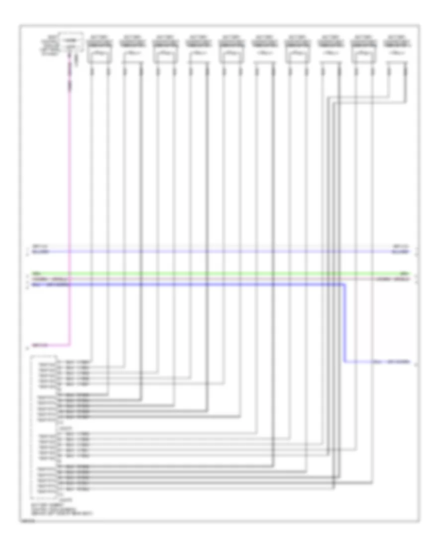
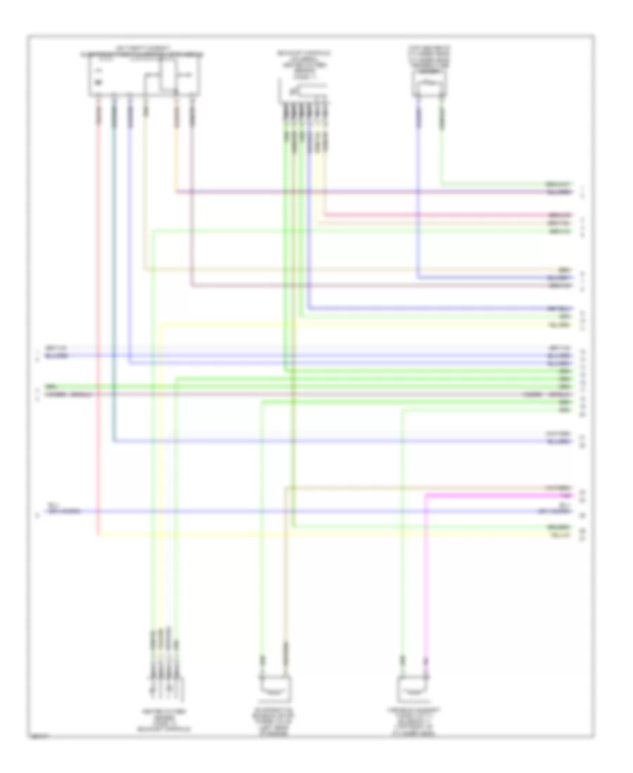
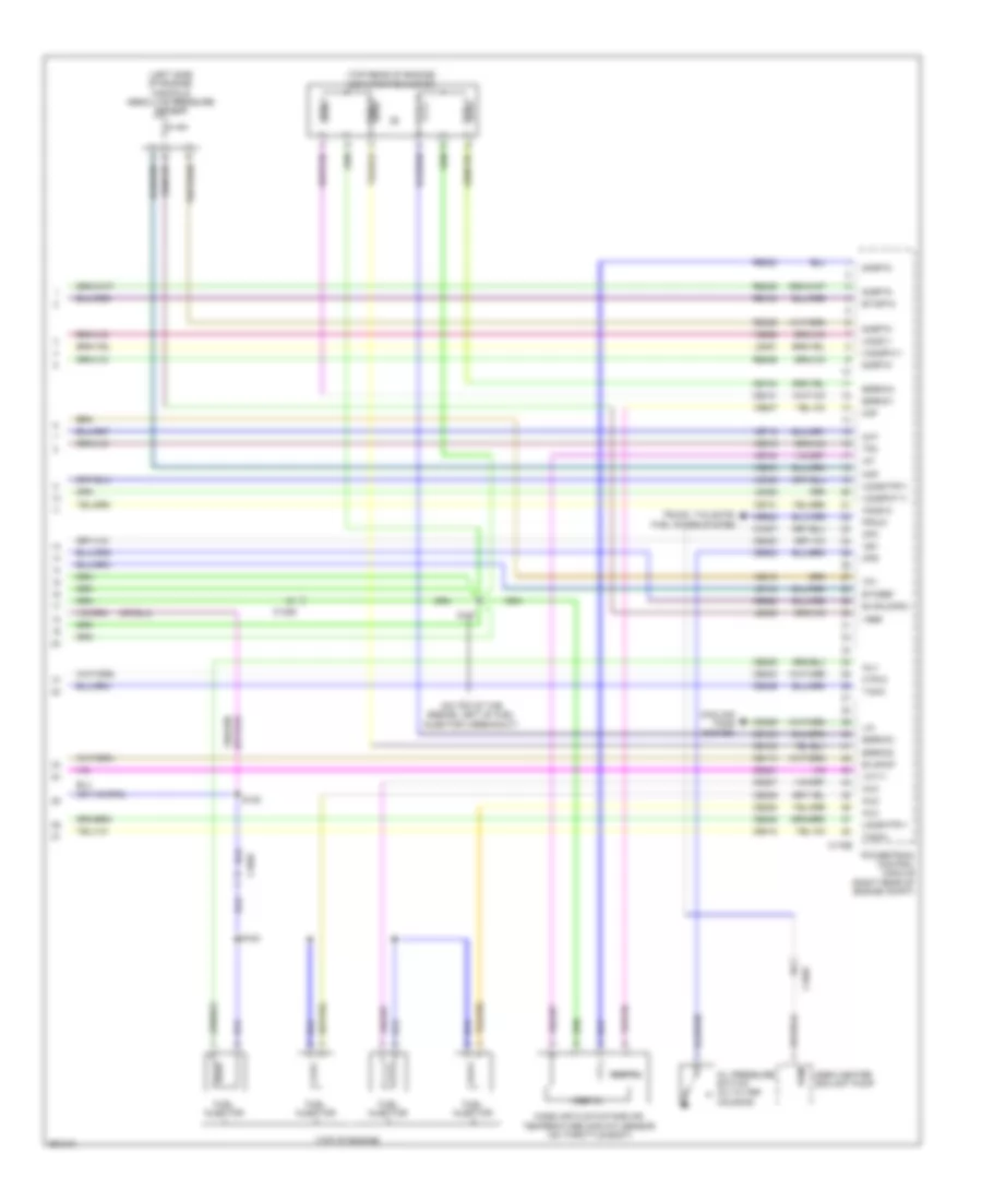
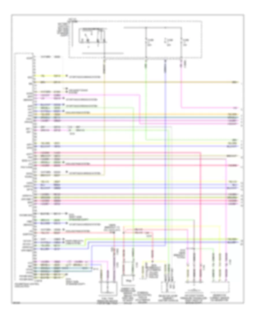
- (exhaust manifold) universal heated oxygen sensor (ho2s) 11
- (on throttle body) electronic throttle control (etc) module
- (top center of cylinder head) cylinder head temperature sensor
- Evaporative emission (evap) purge valve (left rear of engine)
- Heated oxygen sensor (ho2s) 12 (exhaust manifold)
- Nca
- Variable camshaft timing (vct11) solenoid 11 (top front of cylinder head)
2.0L Hybrid, Engine Performance Wiring Diagram (9 of 9) for Ford Fusion S 2013
List of elements for 2.0L Hybrid, Engine Performance Wiring Diagram (9 of 9) for Ford Fusion S 2013:
- (left side of engine) manifold absolute pressure sensor
- (on top of the engine, left of fuel injector 4 breakout)
- (top of engine)
- (top rear of engine) egr stepper motor
- C1026
- C175e
- Cabin heater coolant pump
- Ce101
- Ce102
- Ce103
- Ce104
- Ce113
- Ce205
- Ce206
- Ce207
- Ce208
- Ce233
- Ce235
- Ce412
- Ce420
- Ce421
- Ce426
- Ce622
- Ce908
- Ch307
- Cht
- Coil 1
- Coil 2
- Coil 3
- Coil 4
- Cooling fans system
- Cpc
- Digital
- Egrmc1
- Egrmc2
- Egrmc3
- Egrmc4
- Etcref
- Etcrtn
- Evapcp
- Evapldpsv
- Ffduc
- Fuel injector
- Ho2s12
- Htr12
- Iat
- Inj1
- Inj2
- Inj3
- Inj4
- Le134
- Le423
- Le448
- Le451
- Le452
- Lin
- Maf
- Map
- Mass air flow/intake air temperature (maf/iat) sensor (on throttle body)
- Oil pressure switch (oil filter housing)
- Ops
- Powertrain control module (right rear of engine compt)
- Pwm
- Re134
- Re320
- Re329
- Re405
- Re406
- S120
- S147
- S153
- Sigrtn
- Tacm+
- Tacm-
- Tp1
- Tp2
- Trunk, tailgate, fuel doors system
- Uo2s11
- Uo2shtr11
- Uo2spc11
- Uo2spct11
- Vbv
- Vct11
- Vdn06
- Ve712
- Ve731
- Ve740
- Ve803
- Ve807
- Ve818
- Ve819
- Ve826
- Vref
- Vref 5v
2.5L
2.5L, Engine Performance Wiring Diagram (1 of 5) for Ford Fusion S 2013
List of elements for 2.5L, Engine Performance Wiring Diagram (1 of 5) for Ford Fusion S 2013:
- (near breakout to coil on plug 3) s126
- 15a
- 20a
- Aat
- Accr
- Acpt
- Air conditioning pressure transducer (right front of engine compt)
- Air conditioning system
- Ambient air temperature sensor (behind right end of front grille)
- App1
- App2
- Apprtn1
- Apprtn2
- Appvref1
- Appvref2
- Battery junction box (bjb) (left side of engine compt)
- Bcs2 alt
- Bpp
- Bps
- C1010
- C1035a
- C134
- C145
- C146
- C1551b
- C219
- C2414a
- C315
- Canv
- Cbb07
- Cbb26
- Cbb49
- Ccb08
- Cdc10
- Cdc12
- Cdc15
- Cdc35
- Cdc54
- Ce114
- Ce237
- Ce436
- Cec01
- Cec02
- Ces09
- Cet42
- Cet43
- Ch302
- Computer data lines system
- Cooling fans system
- Cr115
- Fpc
- Fpm
- Fppwr
- Ftp
- Fuel tank pressure sensor (top of fuel tank)
- Fuse
- G104 (right side of engine compt)
- Gd113
- Gencom
- Generator current sensor (on generator)
- Genmon
- Hfc
- Hot at all times
- Hs can +
- Hs can -
- Iat
- Ies
- Isp r
- Le136
- Le137
- Le230
- Le423
- Lfc
- Lin
- Mafrtn
- Mafs
- Nca sst +
- Nca sst -
- Nca sst rtn
- Pcm power relay
- Pcm wake
- Pcmrc
- Power gnd
- Powertrain control module (pcm)
- Re136
- Re137
- Re320
- Re407
- Ref
- S112
- S133 (near breakout to pcm)
- S205 (in breakout to steering column control module)
- Selector lever assembly (center console)
- Sigrtnc
- Smc
- Smcs
- Smr
- Sst +
- Sst -
- Starting/charging system
- Steering column control module (on steering column)
- Vdb04
- Vdb05
- Vdc61
- Vdn06
- Ve225
- Ve462
- Ve518
- Ve701
- Ve702
- Ve740
- Ve750
- Ve807
- Ve922
- Vh433
- Vpwr
- Vref
2.5L, Engine Performance Wiring Diagram (2 of 5) for Ford Fusion S 2013
List of elements for 2.5L, Engine Performance Wiring Diagram (2 of 5) for Ford Fusion S 2013:
- (under right rear of vehicle) evap canister vent control solenoid
- 10a
- 6f35 transmission (left side of transmission)
- Accelerator pedal position (app) sensor (left side of dash)
- Battery junction box (bjb) (left side of engine compt)
- Body control module (left end of dash)
- C1010
- C1035a
- C219
- C2280c
- C2280h
- Digital
- Fuel pump (fet)
- Fuel pump on (fet)
- Fuel pump relay
- Fuse
- Fuse 30a
- Fuse 5a
- Hot at all times
- Hot in start or run
- Lpc
- Mass air flow/ intake air temperature (maf/iat) sensor (left front of engine compt)
- Micro
- Oss
- Oss/tr gnd
- Oss/tr vpwr
- Pcm wake up (fet)
- Pcm wakeup sply
- S113
- S120
- S204 (near breakout to coil on plug 3)
- Ssa
- Ssb
- Ssc
- Ssd
- Sse
- Tcc
- Tft
- Tft sig rtn
- Tr-p
- Trs
- Tspc
- Vref 5v
2.5L, Engine Performance Wiring Diagram (3 of 5) for Ford Fusion S 2013
List of elements for 2.5L, Engine Performance Wiring Diagram (3 of 5) for Ford Fusion S 2013:
- (in breakout to transmission)
- (in breakout to transmission) s141
- (left front of luggage compt) fuel pump control module
- (near breakout to fuel injector 1)
- (not used)
- (rear side of transmission) turbine shaft speed (tss) sensor
- (top of fuel tank) fuel pump assembly
- C1010
- C1026
- C1551t
- C215
- C248
- C315
- Ce225
- Ce233
- Ce515
- Ce608
- Cet05
- Cet06
- Cet07
- Cet08
- Cet09
- Cet10
- Cet18
- Cet25
- Cet34
- Computer data lines system
- Fpc
- Fpm
- Fppwr
- Fprtn
- Fuel sender return
- Fuel sender signal
- G304 (left "c" pillar)
- Gd304
- Gnd
- Heated oxygen sensor (ho2s) 12 (rear of exhaust manifold)
- Ho2s-12
- Hs3 can+
- Hs3 can-
- Htr-12
- Instrument cluster (ic)
- Le111
- Lpc
- Nca
- Oss
- Powertrain control module (pcm)
- Re406
- Re515
- Ret24
- S142
- S156
- S419
- Sigrtnt
- Ssa
- Ssb
- Ssc
- Ssd
- Sse
- Tcc
- Tcs
- Tft
- Trs
- Trs/oss vpwr
- Tspc
- Tss
- Tss/oss/tr gnd
- Ve518
- Ve731
- Vet26
- Vet27
- Vet32
- Vet33
- Vper fuel
2.5L, Engine Performance Wiring Diagram (4 of 5) for Ford Fusion S 2013
List of elements for 2.5L, Engine Performance Wiring Diagram (4 of 5) for Ford Fusion S 2013:
- (front of engine) knock sensor
- (left rear of engine) evaporative emission (evap) purge valve
- (oil filter housing)
- (top rear of engine) egr stepper motor
- Coil
- Crankshaft position sensor (lower right front of engine block)
- Electronic throttle control (etc) motor (on throttle body)
- Exterior lights system
- G101 (left front of engine compt)
- Oil pressure switch
- S147
- S204
- Stoplamp switch (under left side of dash)
- Variable camshaft timing 11 (vct) solenoid (top front of cylinder head)
2.5L, Engine Performance Wiring Diagram (5 of 5) for Ford Fusion S 2013
List of elements for 2.5L, Engine Performance Wiring Diagram (5 of 5) for Ford Fusion S 2013:
- (left rear of engine) manifold absolute pressure (map) sensor
- (top of engine)
- (top of intake manifold) fuel injectors
- (upper right side of engine) cylinder head temperature sensor
- C1026
- C1551e
- Camshaft position sensor 11
- Ce101
- Ce102
- Ce103
- Ce104
- Ce113
- Ce205
- Ce206
- Ce207
- Ce208
- Ce235
- Ce303
- Ce304
- Ce305
- Ce306
- Ce412
- Ce422
- Ce426
- Cht
- Cmc24
- Cmp 1
- Coil on plug (cop) 1
- Coil on plug (cop) 2
- Coil on plug (cop) 3
- Coil on plug (cop) 4
- Cop1a
- Cop2d
- Cop3b
- Cop4c
- Cpk+
- Cpk-
- De135
- Egrmc1
- Egrmc2
- Egrmc3
- Egrmc4
- Etcref
- Etcrtn
- Evapcp
- Ignition transformer capacitor (top rear of engine)
- Inj1
- Inj2
- Inj3
- Inj4
- Ks1+
- Ks1-
- Le111
- Le134
- Le423
- Le448
- Le451
- Le452
- Map
- Ops
- Powertrain control module (pcm)
- Re134
- Re135
- Re323
- Re405
- S144
- S146
- S153 (near breakout to fuel injector 2)
- Shdrtn
- Sigrtn
- Tacm+
- Tacm-
- Tp2
- Tps1
- Universal heated oxygen sensor (ho2s) 11 (rear of exhaust manifold)
- Uo2s11
- Uo2sgref 11
- Uo2shtr (or htr-11)
- Uo2spc 11
- Uo2spct 11
- Vct 11
- Ve706
- Ve711
- Ve712
- Ve801
- Ve803
- Ve818
- Ve819
- Ve826
- Vref