
HORN
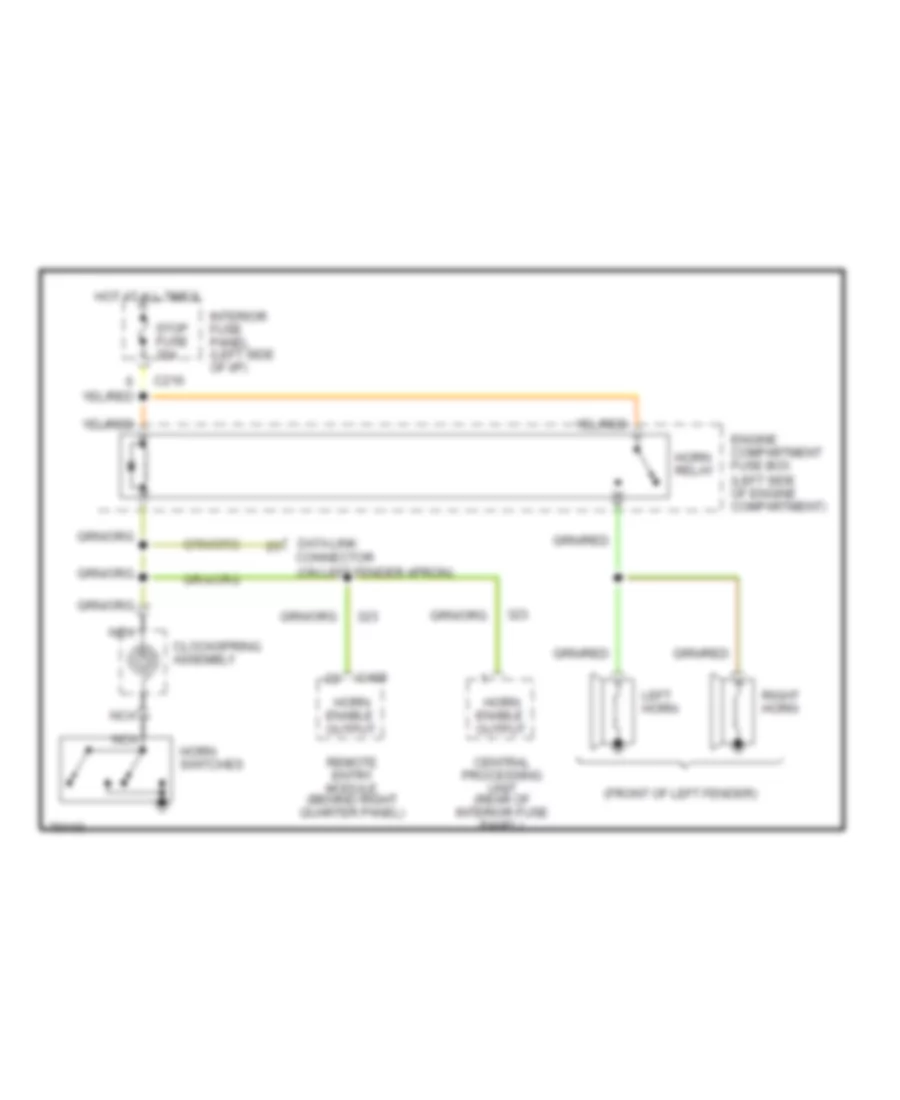
Horn Wiring Diagram for Ford Probe GT 1995
List of elements for Horn Wiring Diagram for Ford Probe GT 1995:
AIR CONDITIONINGANTI-THEFTANTI-LOCK BRAKESCOOLING FANCOMPUTER DATA LINESEXTERIOR LIGHTSDEFOGGERSENGINE PERFORMANCECRUISE CONTROLHEADLIGHTSINTERIOR LIGHTSGROUND DISTRIBUTIONHORNPOWER DISTRIBUTIONPOWER ANTENNAPOWER TOP/SUNROOFPOWER MIRRORSPOWER DOOR LOCKSRADIOPOWER SEATSPOWER WINDOWSSHIFT INTERLOCKSSTARTING/CHARGINGINSTRUMENT CLUSTERSUPPLEMENTAL RESTRAINTSWARNING SYSTEMSTRANSMISSIONWIPER/WASHER