INSTRUMENT CLUSTER
Instrument Cluster Wiring Diagram (1 of 2) for Ford F-Super Duty 1996

List of elements for Instrument Cluster Wiring Diagram (1 of 2) for Ford F-Super Duty 1996:
- (behind bottom of right cowl panel)
- (behind lower center of i/p)
- (behind lower right side of i/p, below glove compt)
- (left front of engine compt, on upper radiator support)
- (left side of safety wall)
- 20 ohms
- 4x4 ind.
- 500 ohms
- A10
- A11
- A12
- A13
- A14
- Acc
- Air bag ind.
- Anti-lock brake ind.
- B10
- B11
- B12
- B13
- Bat
- Brake fluid level
- Brake warning ind.
- Charge ind.
- Check engine ind.
- Chime module
- Conn a
- Conn b
- Conn c
- Control
- Coolant temp. gauge
- Diesel only
- Diesel warning lamps display
- Enable psom programming connector
- Engine warning ind.
- Except diesel
- Exterior lights system (multi-function switch)
- Fasten seat belt ind.
- Fuel gauge
- Fuel water switch (right side of engine, on bottom of fuel filter/heater)
- Fuse 10a
- Fuse 15a
- Fuse 4a
- Fuse panel
- G108
- G200 (behind bottom of left cowl panel)
- G203
- Gas over 8500 gvwr
- Gas under 8500 gvwr and all diesel
- Generator/ voltage regulator
- Gnd
- Headlights system (multi-function switch)
- Hi beam ind.
- Hot at all times
- Hot in run
- Hot in run or start
- Hot w/ light sw in head or park
- Ign (run)
- Ignition switch
- Illumination lamps
- Instrument cluster
- Left turn ind.
- Lock
- Low range ind.
- Mechanical shift only
- Module
- Off
- Oil press. gauge
- Overheat warning switch (left front of engine)
- Plugged fuel filter ind.
- Plugged fuel filter switch (right side of engine, in fuel filter/heater housing)
- Powertrain
- Powertrain control module (left side of safety wall)
- Programmable speedometer/ odometer module
- Red
- Red/pnk
- Right turn ind.
- Run
- Solid state
- Speed control servo/ amplifier assembly (left side of engine compt, near brake master cylinder)
- Start
- Tachometer
- Test
- Volt- meter
- Vss input
- Vss output
- Vss return
- W/ tach
- W/o tach
- Wait-to-start ind.
- Warning
- Water-in- fuel ind.
- Water-in- fuel sensor (right side of engine, near fuel filter)
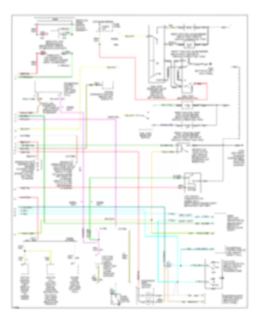
Instrument Cluster Wiring Diagram (2 of 2) for Ford F-Super Duty 1996
List of elements for Instrument Cluster Wiring Diagram (2 of 2) for Ford F-Super Duty 1996:
- (5.0l & 5.8l- (left rear of engine, near intake manifold)
- (5.0l & 5.8l-lower left front of of engine, near oil filter) (7.3l & 7.5l-top center rear of engine)
- (behind right side of i/p, behind glove compt)
- (below right center of
- (below right rear of
- (left rear of engine
- (left rear of engine compt,
- 4x2
- 4x4
- 4x4 hi/low indicator switch (below vehicle, on front of transfer case)
- Air bag diagnostic monitor (behind left side of i/p)
- Brake fluid level switch (left rear of engine compt, on brake fluid reservoir)
- Compt, on bracket)
- Data link connector
- Daytime running lamps module (front left side of lower radiator support)
- Diesel
- Diesel only
- Diesel w/ tach
- Elect. shift
- Electronic shift control module (behind right cowl panel)
- Electronic shift control switch
- Engine coolant temperature sender (4.9l-right side of engine) (except 4.9l-top left front of engine)
- Engine oil pressure switch (4.9l-lower left rear of engine, near oi filter)
- Front
- Front tank fuel gauge sender
- Front tank fuel pump/ fuel gauge sender (below right center of vehicle, in front fuel tank)
- Fuel tank selector switch
- Fuel tank selector valve (under left center of vehicle, on left frame rail)
- Fuse 6 15a
- Fuse panel
- G108 (left front of engine compartment, on upper radiator support)
- G200 (bottom of left cowl panel)
- Gas
- Gasoline
- Hot in acc or run
- Ignition coil (4.9l-left front of engine, forward distributor)
- Ignition control module (left rear of engine compt, on fender apron)
- Link connector
- Low
- Low vacuum warning switch (diesel only) (right side of engine compt., behind right battery)
- Mech. shift
- Nca
- On bracket)
- Only
- Park brake switch
- Power- train control module (left side of safety wall)
- Powertrain control module (left side of safety wall)
- Powertrain control module (left side of safety wall)
- Rabs data
- Rear
- Rear anti-lock brake module
- Rear axle speed sensor (on axle assembly)
- Rear tank fuel gauge sender
- Rear tank fuel pump/ fuel gauge sender (below right rear of vehicle, in rear fuel tank)
- Red
- Red/
- Red/ pnk
- Red/pnk
- Solid state
- Vehicle, in front fuel tank)
- Vehicle, in rear fuel tank)
- W/ drl
- W/o drl