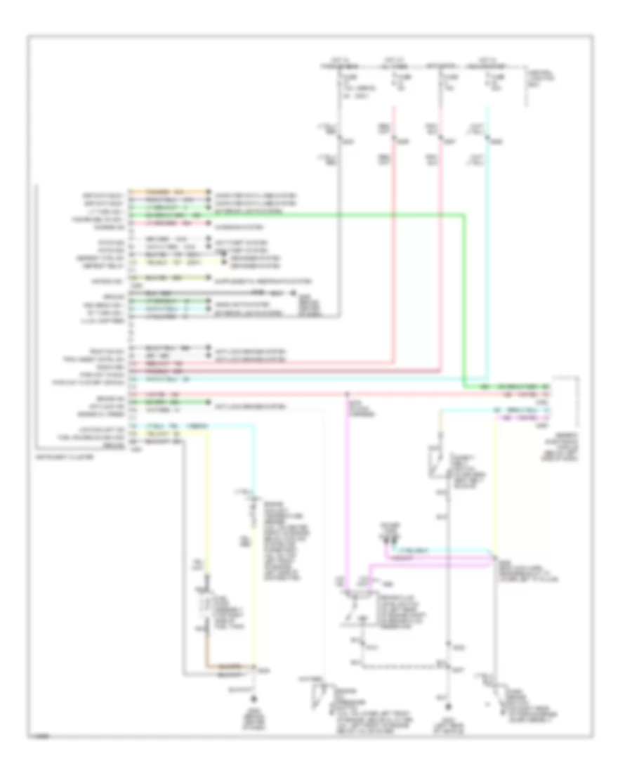
INSTRUMENT CLUSTER
Instrument Cluster Wiring Diagram for Ford Mustang GT 2000
List of elements for Instrument Cluster Wiring Diagram for Ford Mustang GT 2000:
- (1999-00)
- (2001)
- Air bag ind -
- Anti-lock brakes system
- Anti-theft system
- Antilock ind
- Brake fluid level switch (in left rear of engine compt, on brake fluid reservoir)
- Brake ind
- C250
- C251
- C293
- C352
- Central junction box
- Charge ind
- Charging system
- Computer data lines system
- Defogger system
- Defrost ctrl sw
- Defrost relay
- Engine coolant temperature sender (3.8l: on center front of engine, below cooling system air purge port, 4.6l: on top left front of engine, left side of distributor)
- Engine oil press
- Engine oil pressure switch (3.8l: on lower left front of engine, above oil filter, 4.6l: left front of engine below valve cover)
- Exterior lights system
- Fasten belts ind +
- Fuel gauge & slosh mod
- Fuel pump assembly (top right side of fuel tank)
- Fuse 10a
- Fuse 15a
- Fuse 20a
- Fuse 5a
- G206 (behind center of dash)
- G404 (left rear of vehicle)
- Generic electronic module (below left side of dash)
- Ground
- Headlights system
- High beam ind +
- Hot at all times
- Hot in park or head
- Hot in run
- Hot in run or start
- Illum lamp feed
- Instrument cluster
- Low
- Low coolant ind
- Lt turn ind +
- Nca
- Park brake switch (on right rear of parking brake lever asembly)
- Pats mod
- Power tops system
- Pwr (hot in run)
- Pwr (hot in start or run)
- Radio mem
- Rt turn ind +
- S101
- S205
- S206
- S230
- S246 (body main harn, near breakout to lower left "a" pillar)
- S257
- S259
- S266
- S276 (in main harness)
- S307
- S322
- Safety belt switch (in driver's seat belt buckle)
- Scp data bus +
- Scp data bus -
- Trac assist cntrl sw
- Traction sw
 English