NAVIGATION
Crew Chief Wiring Diagram for Ford F-450 Super Duty XLT 2014

List of elements for Crew Chief Wiring Diagram for Ford F-450 Super Duty XLT 2014:
- 5vpwr
- 5vtb
- Battery junction box (bjb) (left side of engine compt)
- Body control module (bcm) (right kick panel)
- C2280b
- Cgnd
- Computer data lines system
- Fuse 30a
- Fuse 5a
- G203 (lower left center of dash)
- Gnd
- Gnd1
- Hot at all times
- Hot in start or run
- Hs can+
- Hs can-
- Hsc1-c
- Hsc2-c
- Igrun-c
- Inline fuse (right end of dash)
- Modem-antenna (top center of dash)
- Nca
- Pwr ground
- Red
- Run start
- Rxd
- S272
- S273
- S274
- Telematics module (right end of dash)
- Txd
- Vb1
- Vbatt
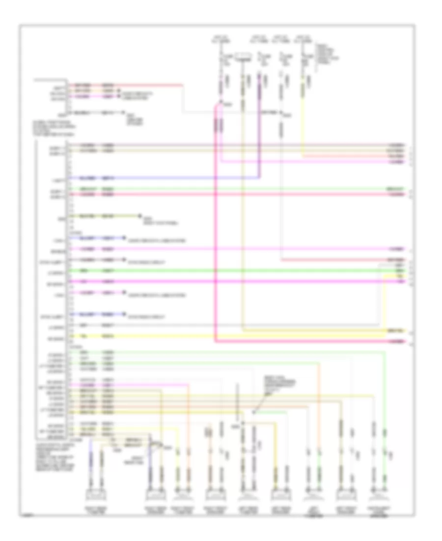
Navigation Wiring Diagram, with Sony (1 of 3) for Ford F-450 Super Duty XLT 2014
List of elements for Navigation Wiring Diagram, with Sony (1 of 3) for Ford F-450 Super Duty XLT 2014:
- (body main wiring harness, near breakout to c311) s291
- (right rear cab)
- Audio digital signal processing (dsp) module (crew cab: base of right "c" pillar) (super cab: center rear of cab floor)
- Body control module (right kick panel)
- C207
- C2280a
- C2280b
- C2280d
- C3154a
- C3154b
- C3154c
- C555
- C655
- C755
- C855
- Cls32
- Computer data lines system
- Enable
- Fuse 15a
- Fuse 20a
- Fuse 5a
- G201 (center of dash)
- G302 (right kick panel)
- Gd114
- Gd139
- Global positioning system module (gpsm) (w/ sync) (top center of dash)
- Gnd
- Hazard
- Hot at all times
- I can +
- I can -
- Instrument panel speaker
- Ip spkr +
- Ip spkr -
- Left front speaker
- Left front tweeter
- Left rear speaker
- Left rear tweeter
- Lf spkr +
- Lf spkr -
- Lf tweeter +
- Lf tweeter -
- Lr spkr +
- Lr spkr -
- Ms can+
- Ms can-
- Nca
- Rf spkr +
- Rf spkr -
- Rf tweeter +
- Rf tweeter -
- Right front speaker
- Right front tweeter
- Right rear speaker
- Right rear tweeter
- Rme06
- Rme07
- Rme08
- Rme09
- Rme10
- Rme11
- Rme12
- Rme17
- Rme18
- Rme22
- Rme55
- Rme80
- Rr spkr +
- Rr spkr -
- S222
- S228
- S292
- S300
- S301
- Sbp19
- Sbp29
- Sme23
- Subw 1+
- Subw 1-
- Subw 2+
- Subw 2-
- Sync alert +
- Sync alert -
- Sync radio circuit
- V batt
- Vbatt
- Vdb06
- Vdb07
- Vdb13
- Vdb14
- Vme06
- Vme07
- Vme08
- Vme09
- Vme10
- Vme11
- Vme12
- Vme17
- Vme18
- Vme22
- Vme55
- Vme80
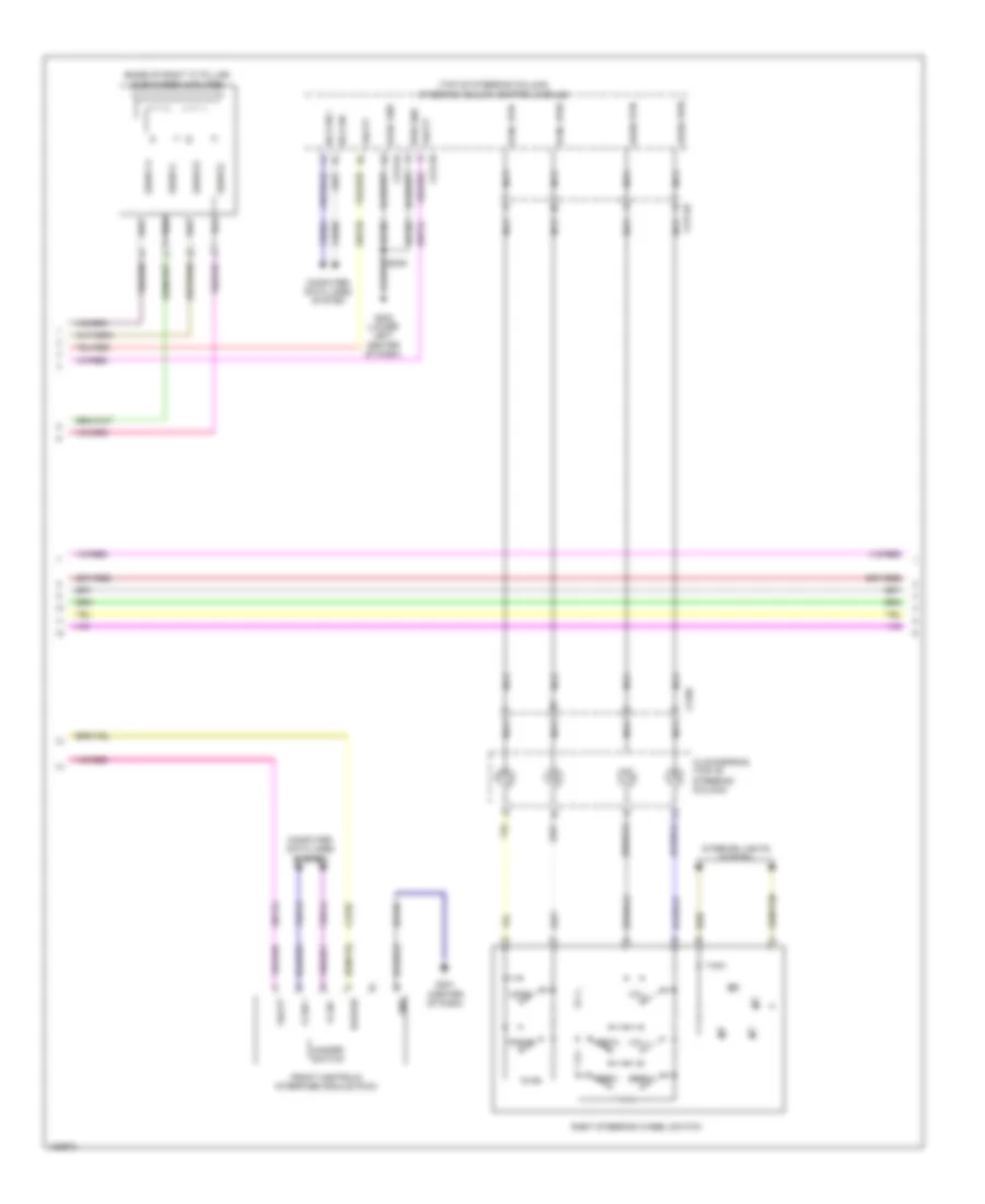
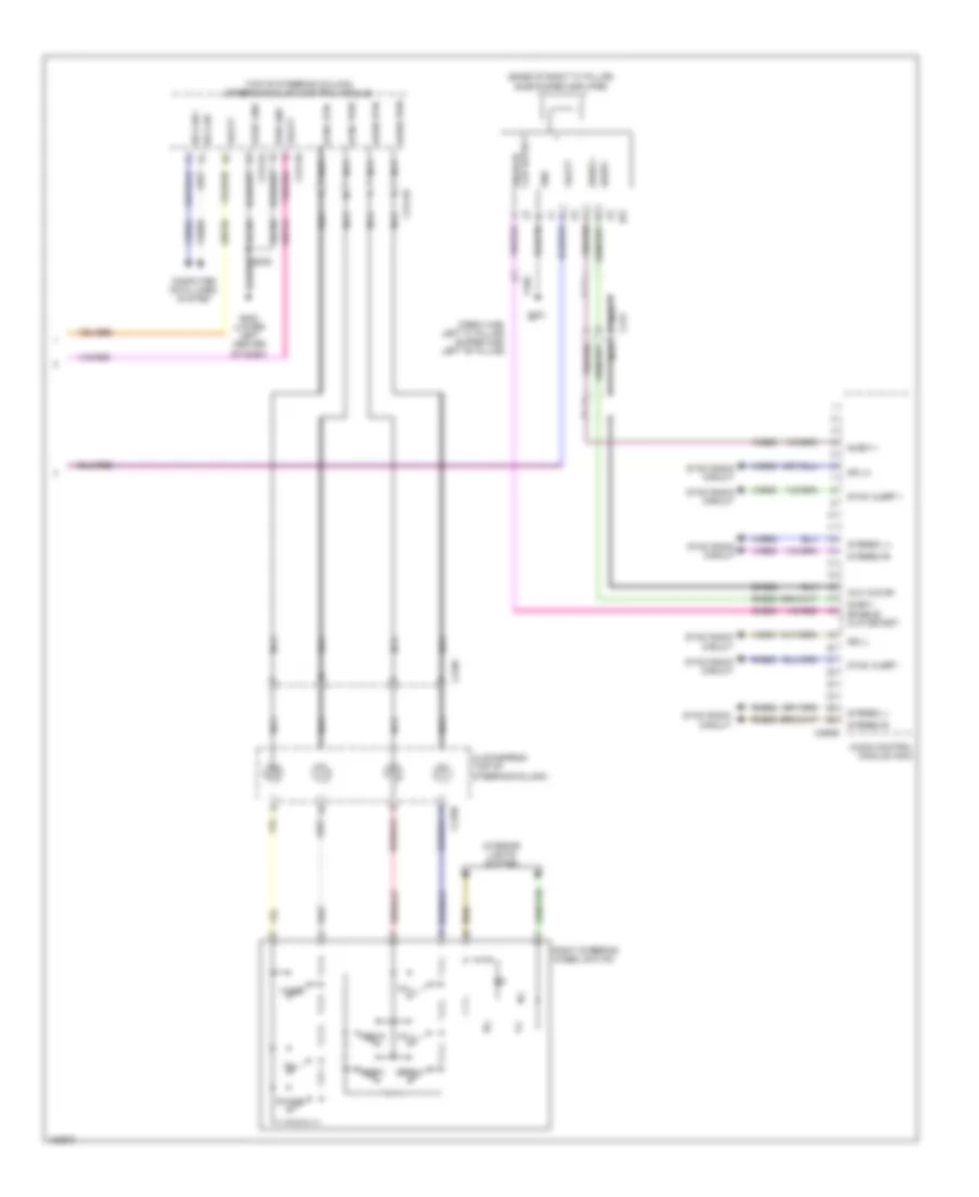
Navigation Wiring Diagram, with Sony (2 of 3) for Ford F-450 Super Duty XLT 2014
List of elements for Navigation Wiring Diagram, with Sony (2 of 3) for Ford F-450 Super Duty XLT 2014:
- (base of right "c" pillar) subwoofer amplifier
- (top of steering column)
- Audio pwr
- Audio rtn
- C218c
- C2414a
- C2414b
- C2414d
- Clockspring (top of steering column)
- Cls32
- Computer data lines system
- Front controls interface module (fcim)
- G201 (center of dash)
- G202 (lower left center of dash)
- Gd184
- Gd185
- Gnd
- Hazard
- Hazard switch
- Hs can +
- Hs can -
- I can +
- I can -
- Interior lights system
- Logic gnd
- Media
- Nca
- Phone
- Pwr gnd
- Right steering wheel switch
- S239
- Sbp24
- Sbp26
- Seek+
- Seek-
- Steering column control module
- Subw 1+
- Subw 1-
- Subw 2+
- Subw 2-
- Sync pwr
- Sync rtn
- Vbatt
- Vdb04
- Vdb05
- Vdb13
- Vdb14
- Voice
- Vol+
- Vol-
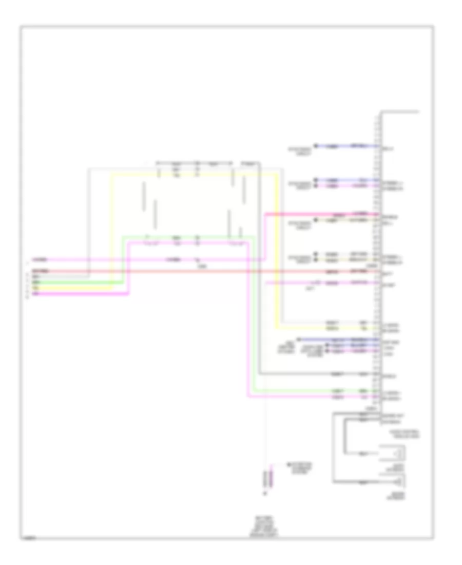
Navigation Wiring Diagram, with Sony (3 of 3) for Ford F-450 Super Duty XLT 2014
List of elements for Navigation Wiring Diagram, with Sony (3 of 3) for Ford F-450 Super Duty XLT 2014:
- Am/fm antenna
- Amp gnd
- Antenna
- Audio control module (acm)
- Batt
- Battery junction box (bjb) (left side of engine compt)
- C211
- C265
- C290a
- C290b
- Cdc38
- Computer data lines system
- Dme17
- Enable
- G201 (center of dash)
- Gd114
- I can+
- I can-
- Lf spkr +
- Lf spkr -
- Nca
- Rf spkr +
- Rf spkr -
- Rme17
- Rme18
- Rme52
- Rme53
- Sbp29
- Sdars ant
- Sdars antenna
- Sdl-h
- Sdl-l
- Shield
- Sme23
- Start
- Starting/ charging system
- Stereo l+
- Stereo l-
- Stereo r+
- Stereo r-
- Sync radio circuit
- Vdb13
- Vdb14
- Vme17
- Vme18
- Vme52
- Vme53
- Vme90
- Vme91
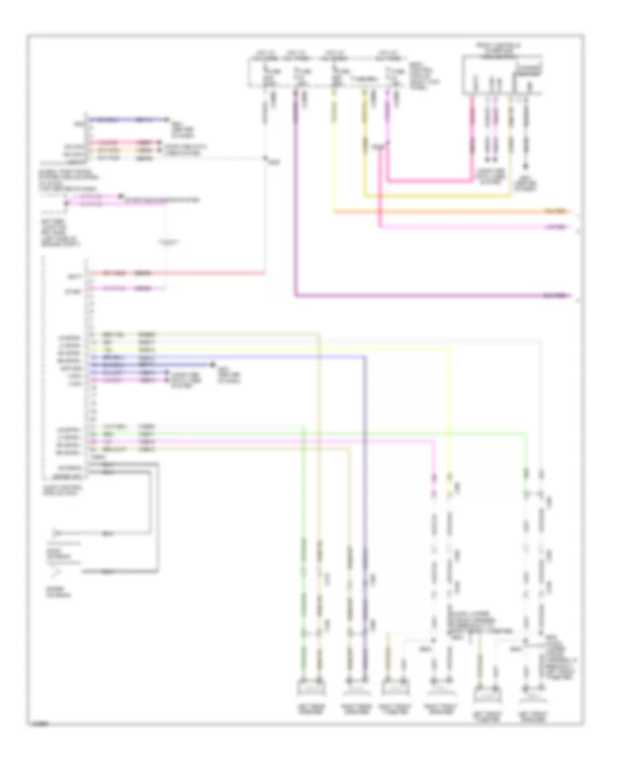
Navigation Wiring Diagram, without Sony (1 of 2) for Ford F-450 Super Duty XLT 2014
List of elements for Navigation Wiring Diagram, without Sony (1 of 2) for Ford F-450 Super Duty XLT 2014:
- (audio jumper wiring harness, in breakout to right front tweeter) s602
- Am/fm antenna
- Amp gnd
- Antenna
- Audio control module (acm)
- Batt
- Battery junction box (bjb) (left side of engine compt)
- Body control module (right kick panel)
- C211
- C212
- C2280a
- C2280b
- C2280d
- C265
- C290a
- C510
- C555
- C610
- C655
- C756
- C856
- Cdc38
- Cls32
- Computer data lines system
- Front controls interface module (fcim)
- Fuse 15a
- Fuse 20a
- Fuse 5a
- G201 (center of dash)
- Gd114
- Gd184
- Global positioning system module (gpsm) (w/ sync) (top center of dash)
- Gnd
- Hazard
- Hazard switch
- Hot at all times
- I can +
- I can -
- I can+
- I can-
- Left front speaker
- Left front tweeter
- Left rear speaker
- Lf spkr +
- Lf spkr -
- Lr spkr +
- Lr spkr -
- Ms can+
- Ms can-
- Rf spkr +
- Rf spkr -
- Right front speaker
- Right front tweeter
- Right rear speaker
- Rme09
- Rme12
- Rme17
- Rme18
- Rr spkr +
- Rr spkr -
- S222
- S228
- S502 (audio jumper wiring harness, in breakout left front tweeter)
- S503
- S603
- Sbp24
- Sbp29
- Sdars ant
- Sdars antenna
- Start
- Starting/charging system
- Vbatt
- Vdb06
- Vdb07
- Vdb13
- Vdb14
- Vme09
- Vme12
- Vme17
- Vme18
Navigation Wiring Diagram, without Sony (2 of 2) for Ford F-450 Super Duty XLT 2014
List of elements for Navigation Wiring Diagram, without Sony (2 of 2) for Ford F-450 Super Duty XLT 2014:
- (base of right "c" pillar) subwoofer amplifier
- (crew cab: left "c" pillar) (super cab: left "b" pillar)
- (top of steering column) steering column control module
- Audio control module (acm)
- Audio pwr
- Audio rtn
- Aux aud sh
- C212
- C218b
- C218c
- C2414a
- C2414b
- C2414d
- C265
- C290b
- Clockspring (top of steering column)
- Computer data lines system
- Dme22
- Enable/ clip detect
- G202 (lower left center of dash)
- G301
- Gd185
- Gnd
- Hs can +
- Hs can -
- Interior lights system
- Logic gnd
- Media
- Nca
- Phone
- Pwr gnd
- Right steering wheel switch
- Rme22
- Rme52
- Rme53
- Rme80
- S239
- Sbp24
- Sbp26
- Sdl-l
- Seek+
- Seek-
- Sme23
- Spl-h
- Stereo l+
- Stereo l-
- Stereo r+
- Stereo r-
- Subw +
- Subw -
- Subw - enable/ clip detect
- Sync alert +
- Sync alert -
- Sync pwr
- Sync radio circuit
- Sync rtn
- Vbatt
- Vdb04
- Vdb05
- Vme22
- Vme52
- Vme53
- Vme80
- Vme90
- Vme91
- Voice
- Vol+
- Vol-
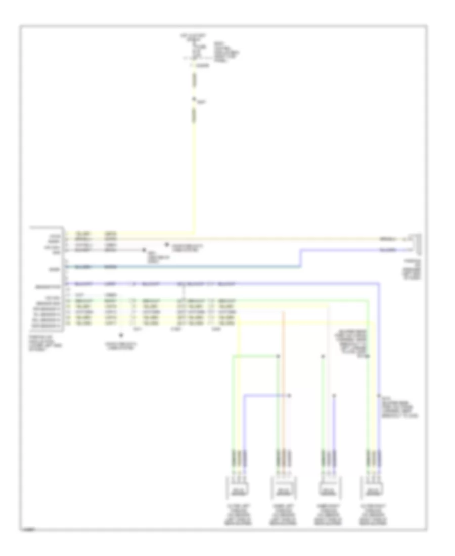
Parking Assistant Wiring Diagram for Ford F-450 Super Duty XLT 2014
List of elements for Parking Assistant Wiring Diagram for Ford F-450 Super Duty XLT 2014:
- (bumper rear park aid wiring harness, near breakout to left license plate lamp) s415
- (left side of rear bumper)
- Body control module (bcm) (right kick panel)
- C1581
- C211
- C2280b
- C408
- Cbp35
- Cmp09
- Computer data lines system
- Fuse 5a
- G201 (center of dash)
- Gd184
- Gnd
- Hot in start or run
- Hs can+
- Hs can-
- Inner left parking aid sensor
- Inner right parking aid sensor (right side of rear bumper)
- Lmp07
- Outer left parking aid sensor (left side of rear bumper)
- Outer right parking aid sensor (right side of rear bumper)
- Parking aid module (pam) (lower left end of dash)
- Parking aid speaker (left end of dash)
- Ril sensor in
- Rir sensor in
- Rmp07
- Rmp09
- Rol sensor in
- Ror sensor in
- S227
- S416 (bumper rear park aid wiring harness, near breakout to c408)
- Sensor gnd
- Sensor pwr
- Sndr+
- Sndr-
- Solid state
- Vdb04
- Vdb05
- Vmp14
- Vmp15
- Vmp16
- Vmp17
- Vpwr
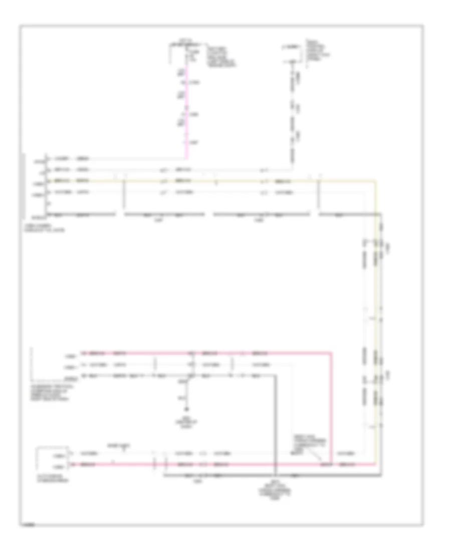
Rear Camera Wiring Diagram for Ford F-450 Super Duty XLT 2014
List of elements for Rear Camera Wiring Diagram for Ford F-450 Super Duty XLT 2014:
- (body main wiring harness, in breakout to c264) s373
- Accessory protocol interface module (premium audio) (right end of dash)
- Auto dimming interior mirror
- Base audio
- Battery junction box (bjb) (left side of engine compt)
- Body control module (right kick panel)
- C1581
- C210
- C2280c
- C264
- C265
- C465
- C497
- Cbb49
- Dmp19
- Fuse 10a
- G201 (center of dash)
- Hot in start or run
- Lin
- Micro
- Nca
- Rmp19
- S340 (body main wiring harness, in breakout to c265)
- S372
- Shield
- Vdn03
- Video +
- Video -
- Video camera (middle of tail gate)
- Video+
- Video-
- Vmp19
- Vpwr