POWER DISTRIBUTION
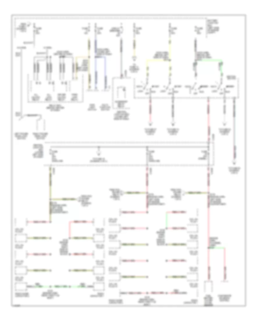
Power Distribution Wiring Diagram (1 of 4) for Ford Cab & Chassis F350 Super Duty 2001

List of elements for Power Distribution Wiring Diagram (1 of 4) for Ford Cab & Chassis F350 Super Duty 2001:
- (center of dash) g206
- (diesel only)
- (diesel w/o dual gen)
- (engine harn, left front of engine compt) s120
- (engne harn, near breakout to starter motor relay) s146
- (in back-up lamp harn, left rear of engine compt) s251
- (left rear of engine compt) bi-fuel relay module
- (left side of engine compt) battery junction box
- (main harn, lower center of dash) s223
- (main harn, near inst cluster breakout) s298
- A/c clutch relay
- Adjustable pedal switch
- Anti-lock brake system module
- Battery junction box (left side of engine compt)
- Bi-fuel
- Bi-fuel power relay
- Blower motor relay
- C104b
- C152
- C154
- C257a
- California
- Cold start heater relay
- Compuvalve module
- Daytime running lamps resistor
- Diesel
- Driver heated seat module
- Driver's seat regulator control switch
- Drl relay block (behind right side of dash)
- Except california
- Fog lamp relay
- From a fuse 23 (diagram 1 of 4)
- Fuel pump relay
- Fuse 10a
- Fuse 15a
- Fuse 20a
- Fuse 30a
- Fuse 3a
- Fuse 40a
- Fuse 5a (diesel w/ dual gen)
- Fuse 60a
- Gasoline
- Generator/ voltage regulator (diesel)
- Generator/ voltage regulator (gasoline)
- Generator/ voltage regulator (secondary: diesel w/ dual gen)
- Glow plug control module
- Glow plug relay
- High to low relay
- I/p relay block (behind left side of dash)
- Idm power relay (diesel)
- Left battery (diesel only)
- Low to high relay
- Manifold intake air heater relay
- Nca
- Passenger heated seat module
- Pcm diode
- Pcm power relay
- Power point
- Radio
- Red
- Right battery
- S147 (near starter motor relay)
- S148 (near starter motor relay)
- S149 (near starter motor relay)
- S290
- Starter motor
- Starter motor relay
- To fuse 17 (diagram 1 of 4)
- To fuse 26 (diagram 2 of 4)
- To fuse 30 (diagram 2 of 4)
- Trailer battery charge relay
- Trailer brakes feed (taped in harness)
- Trailer reversing lamps relay
- Trailer running lamps relay
- Trailer tow relay block (left side of engine compt)
- Transfer case shift relay
- Washer pump relay
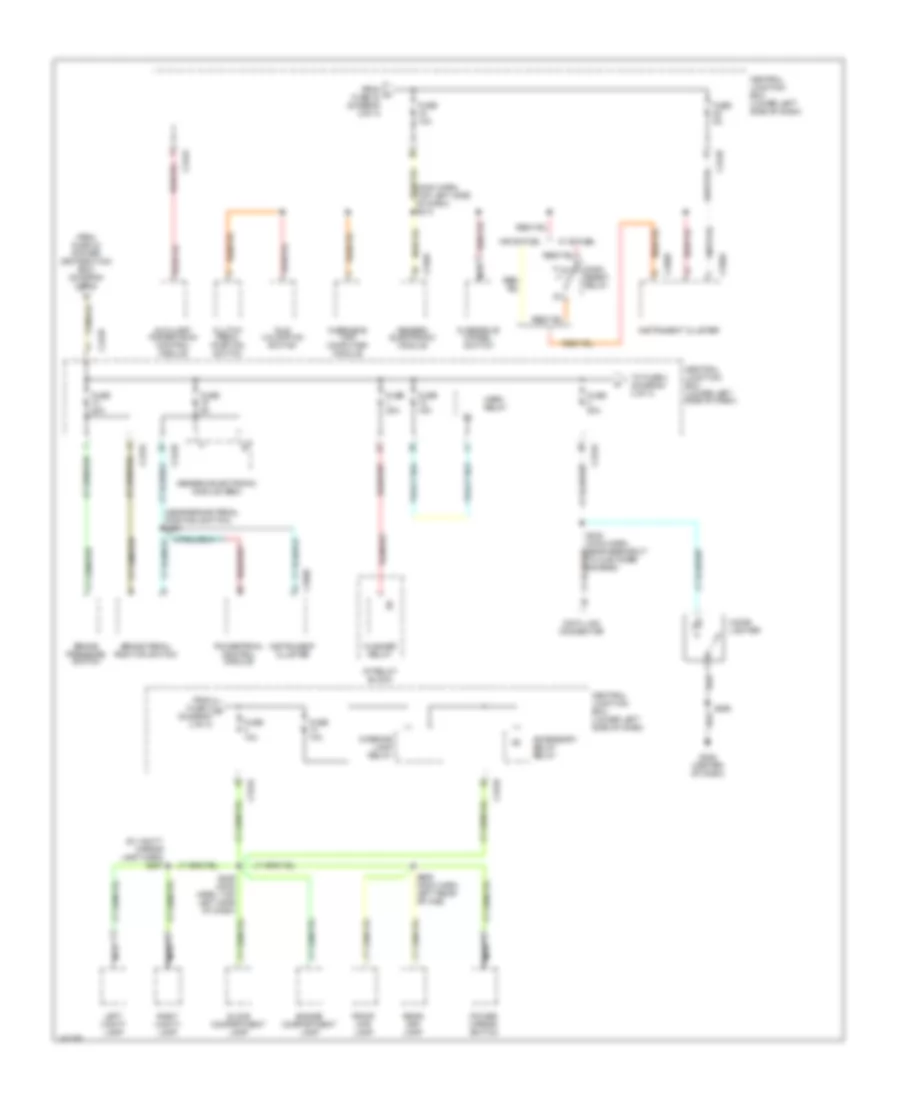
Power Distribution Wiring Diagram (2 of 4) for Ford Cab & Chassis F350 Super Duty 2001
List of elements for Power Distribution Wiring Diagram (2 of 4) for Ford Cab & Chassis F350 Super Duty 2001:
- (engine harn, pia diesel harn) s154
- (main harn, behind left side of dash) s210
- (main harn, behind left side of dash) s212
- (main harn, center of dash) s230
- (main harn, lower left side of dash) s214
- Acc
- Accessory delay relay
- All lock relay
- All unlock relay
- Battery junction box (left side of engine compt)
- C242a
- C242b
- Central junction box (lower left side of dash)
- Circuit breaker 30a
- Coil on plug 1
- Coil on plug 10
- Coil on plug 2
- Coil on plug 3
- Coil on plug 4
- Coil on plug 5
- Coil on plug 6
- Coil on plug 7
- Coil on plug 8
- Coil on plug 9
- Driver unlock relay
- From b fuse 4 (diagram 1 of 4)
- From pcm power relay (diagram 1 of 4)
- Fuel heater/ water in fuel sensor
- Fuse 15a
- Fuse 20a
- Fuse 30a
- Fuse 30a (5.4l gasoline)
- Fuse 30a (6.8l gasoline)
- Fuse 30a (diesel)
- Fuse 50a
- Ignition switch
- Left power door lock switch
- Lock
- Main light switch
- Multi- function switch
- Nca
- Off
- Park lamp relay
- Radio capacitor 1
- Radio noise capacitor 2
- Relay box (behind center of dash)
- Right power door lock switch
- Run
- S130 (engine harn, near throttle body)
- S135 (engine harn, right side of engine block)
- S179 (engine harn, left side of engine compartment)
- S272 (main harn, left side of dash)
- Start
- To fuse 10 (diagram 4 of 4)
- To fuse 13 (diagram 3 of 4)
- To fuse 19 (diagram 3 of 4)
- To fuse 20 (diagram 4 of 4)
- To fuse 22 (diagram 4 of 4)
- To fuse 27 (diagram 4 of 4)
- W/ rke
- W/o rke
- Wastegate solenoid control
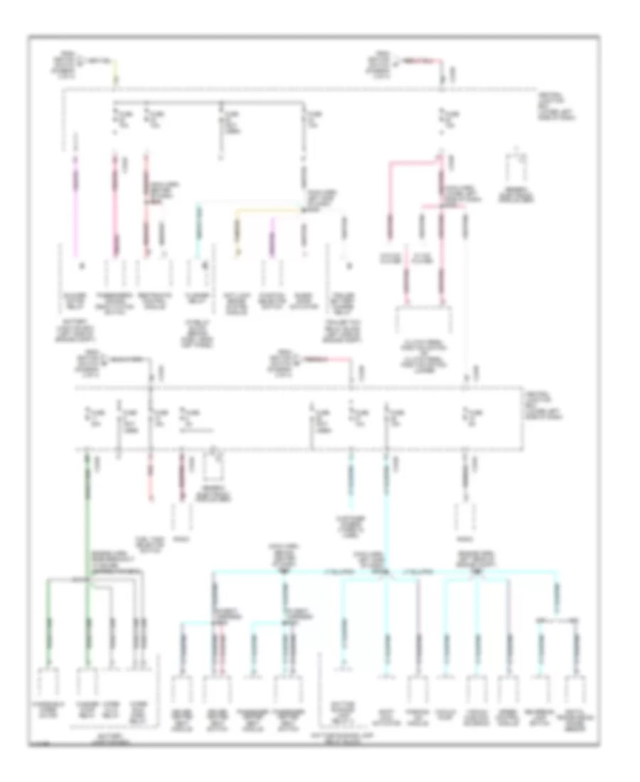
Power Distribution Wiring Diagram (3 of 4) for Ford Cab & Chassis F350 Super Duty 2001
List of elements for Power Distribution Wiring Diagram (3 of 4) for Ford Cab & Chassis F350 Super Duty 2001:
- (in vanity mirror lamp harn) s937
- (main harn, top left side of dash) s213
- (near brake pedal position switch) s221
- 87a
- Accessory delay relay
- Auxiliary powertrain control module
- Brake pedal position switch
- Brake pressure switch
- C240a
- C242a
- C242b
- C250a
- C250b
- Central junction box (lower left side of dash)
- Cigar lighter
- Clutch pedal position switch
- Dash reset relay
- Data link connector
- Engine compartment lamp
- Flasher relay
- From fuse 22 (power distribution box) (diagram 2 of 4)
- From fuse 3 k (diagram 3 of 4)
- From h fuse 30 (diagram 2 of 4)
- Front map lamp
- Fuse 10a
- Fuse 15a
- Fuse 20a
- Fuse 5a
- G206 (center of dash)
- Generic electronic module
- Generic electronic module (gem)
- Glove compartment lamp
- Horn relay
- I/p relay block
- Idle validation switch
- Instrument cluster
- Interior lamp relay
- Left vanity lamp
- Nca
- Overdrive cancel switch
- Overhead trip computer module
- Power mirror switch
- Powertrain control module
- Rear map lamp
- Right vanity lamp
- S229 (main harn, top left side of dash)
- S242 (main harn, near breakout to customer access)
- S290
- S906 (main harn, left rear of cab)
- To fuse 4 (diagram 3 of 4)
- W/ bi-fuel
- W/o bi-fuel
Power Distribution Wiring Diagram (4 of 4) for Ford Cab & Chassis F350 Super Duty 2001
List of elements for Power Distribution Wiring Diagram (4 of 4) for Ford Cab & Chassis F350 Super Duty 2001:
- (engine harn, left rear of engine compt) s124
- (engine harn, near breakout to power distribution box)
- (main harn, behind center of dash) s238
- (main harn, center of dash) s200
- (main harn, left side of dash) s206
- (main harn, left side of dash) s235
- (main harn, lower left side of dash) s275
- A/t
- Anti-lock brake system module
- Battery junction box
- Battery junction box (left side of engine compt)
- Blend door actuator
- Blower motor relay
- C242a
- C242b
- Central junction box (lower left side of dash)
- Clutch pedal position switch or clutch pedal position switch jumper
- Customer access (taped in harn)
- Daytime running lamp relay 2
- Daytime running lamp relay block
- Digital transmission range sensor
- Driver heated seat module
- Driver heated seat switch
- Flasher relay
- From ignition switch (diagram 2 of 4)
- Fuel tank selector switch
- Function selector switch
- Fuse (not used)
- Fuse 10a
- Fuse 15a
- Fuse 30a
- Fuse 5a
- Generic electronic module (gem)
- I/p relay block (behind dash, near inst panel)
- M/t
- Parking aid module
- Passenger heated seat module
- Passenger heated seat switch
- Passenger's air bag deactivation switch
- Radio
- Red
- Restraints control module
- Reversing lamp switch
- S119
- S334
- S335
- Shift lock actuator
- Speed control module
- Tan/red
- Trailer battery charge relay
- Trailer tow relay block (left side of engine compt)
- Vacuum hublock solenoid
- Vacuum pump
- W/ c/d player
- W/o c/d player
- Washer pump relay
- Windshield wiper motor
- Wiper hi/lo relay
- Wiper run/ park relay