POWER DISTRIBUTION
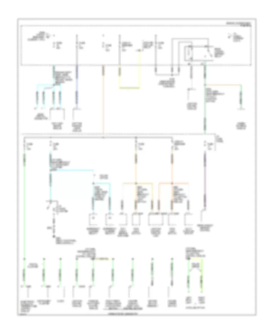
Power Distribution Wiring Diagram (1 of 4) for Ford Crown Victoria S 1998

List of elements for Power Distribution Wiring Diagram (1 of 4) for Ford Crown Victoria S 1998:
- (engine compt harn, near breakout to fuse box) s100
- (i/p harn, behind left side of dash) s283
- (i/p harn, in breakout to blend door actuator) s245
- (near breakout to clock) s213
- (not used)
- (rear harn, near breakout to right rear speaker)
- Air suspension compressor motor/ vent solenoid
- Air suspension/ evo steering module
- Base vehicle and police
- Battery
- C216
- C251
- C520
- Cd changer
- Circuit breaker 7 20a
- Compressor relay
- Cooling fan high relay
- Customer use
- Data link connector
- Driver's door module
- Driver's lumbar switch
- Driver's seat control switch
- Engine compartment fuse box
- Except natural gas
- From a fuse 4 (diagram 1 of 4)
- Front control unit
- Fuel pump prime connector
- Fuel pump relay or fuel valve relay
- Fuse 15a
- Fuse 20a
- Fuse 25a
- Fuse 30a
- Fuse 50a
- Fusible link (12 ga) (gray)
- Generator/ voltage regulator
- High current relay center
- Horn relay
- Instrument cluster (analog)
- Left rear air spring solenoid
- Master window/ door lock control switch
- Natural gas vehicle module
- Nca
- Passenger's lumbar switch
- Passenger's seat control switch
- Pcm power relay
- Police option
- Police option fuse holder
- Police power relay
- Powertrain control module
- Red
- Relay center
- Right front window/ door lock control switch
- Right rear air spring solenoid
- S124 (engine harn, near breakout to fuel pump prime)
- S132 (in breakout to generator voltage regulator)
- S144 (engine compt harn, near breakout to fuse box)
- S155
- S282 (i/p harn, behind left side of dash)
- S406 (rear harn, near breakout to rear air spring solenoid)
- S411
- Starter/ motor solenoid
- Subwoofer amplifier (jbl only)
- To fuse 14 (diagram 2 of 4)
- To fuse 8 (diagram 1 of 4)
- Trunk lid release switch
- W/ keyless entry
- W/ power lumbar
- W/o keyless entry
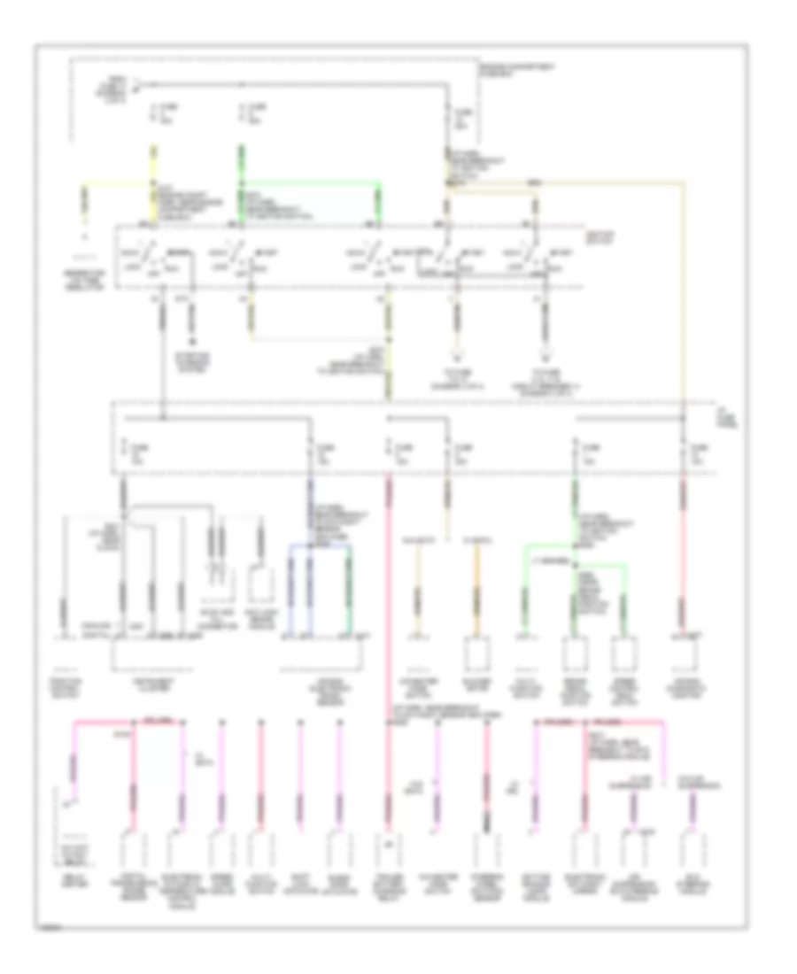
Power Distribution Wiring Diagram (2 of 4) for Ford Crown Victoria S 1998
List of elements for Power Distribution Wiring Diagram (2 of 4) for Ford Crown Victoria S 1998:
- (engine compt harn, near breakout to primary crash sensor) s146
- (i/p harn, near breakout to instrument cluster) s294
- (i/p harn, near breakout to lighting control module) s228
- Anti-lock brake module
- C2029
- C228
- C249
- C255
- C262
- Circuit breaker 20a
- Circuit breaker 30a
- Clock
- Cooling fan low relay
- Day/ night sensor amplifier
- Daytime running lamps module
- Digital cluster
- Electronic automatic temperature control module
- Emergency flasher relay 1
- Emergency flasher relay 2
- Engine compartment fuse box
- Evac and fill connector
- From circuit breaker 7 (diagram 1 of 4)
- Fuse 10a
- Fuse 15a
- Fuse 20a
- Fuse 30a
- Fuse 40a
- G203 (right kick panel, near door sill)
- Hidden antenna module
- I/p cigar lighter
- I/p fuse panel
- Instrument cluster
- Keypad switch assembly
- Left spot light
- Lighting control module
- Lighting control module (lcm)
- Main light switch
- Master window/ door lock control switch
- Multi- function switch
- Nca
- Passive anti-theft system module
- Police option
- Power mirror switch
- Rear window defrost control
- Rear window defrost relay
- Right front window/door lock control switch
- Right spot light
- S153 (near engine compartment fuse box)
- S206
- S252 (main harn, near breakout to multi- function switch)
- S262 (i/p harn, near breakout to lighting control module)
- S285 (i/p harn, near breakout to main light switch)
- S426 (trunk harn, near breakout to relay center)
- To fuse 2 (diagram 3 of 4)
- W/police option
- W/remote keyless entry
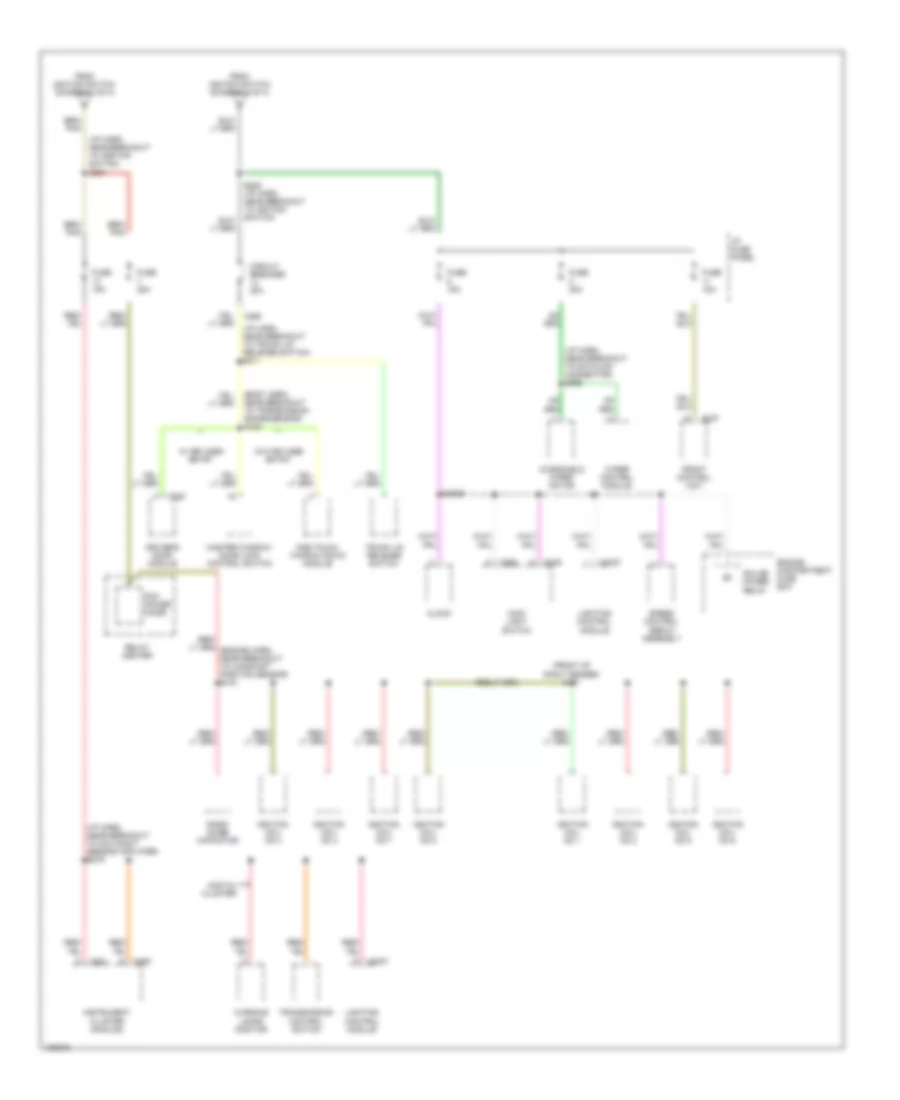
Power Distribution Wiring Diagram (3 of 4) for Ford Crown Victoria S 1998
List of elements for Power Distribution Wiring Diagram (3 of 4) for Ford Crown Victoria S 1998:
- (analog)
- (digital)
- (i/p harn, near breakout to day/night sensor amplifier) s226
- (i/p harn, near breakout to day/night/ sensor amplifier) s269
- (i/p harn, near breakout to ignition switch) s263
- A/c wot cutout relay
- A/c-heater mode switch
- Acc
- Air bag diagnostic monitor
- Air bag electronic crash sensor
- Air suspension/ evo steering module
- Anti-lock brake module
- Blend door actuator
- Blower motor
- Brake pedal position switch
- C216
- C251
- C255
- C256
- C277
- Daytime running lamps module
- Digital transmission range sensor
- Electronic automatic temperature control module
- Electronic day/night mirror
- Engine compartment fuse box
- Evac and fill connector
- Evo steering module
- From fuse 14 (diagram 2 of 4)
- Fuse 10a
- Fuse 15a
- Fuse 30a
- Fuse 50a
- Generator/ voltage regulator
- I/p fuse panel
- Ignition switch
- Instrument cluster
- Lock
- Multi- function switch
- Nca
- Off
- Relay center
- Run
- S139
- S231 (i/p harn, near clock)
- S265 (near brake pedal position switch)
- S272 (i/p harn, near breakout to ignition switch)
- S274 (i/p harn, near breakout to evo steering module)
- Shift lock actuator
- Speed chime module
- Speed control deac switch
- Start
- Starting/ charging system
- Steering wheel rotation sensor
- To fuse 2, 6, 11 & circuit breaker 14 (diagram 4 of 4)
- To fuse 7 & 13 (diagram 4 of 4)
- Traction control switch
- Trailer battery charging relay
- W/ air suspension
- W/ drl
- W/ eatc
- W/o air suspension
- W/o eatc
Power Distribution Wiring Diagram (4 of 4) for Ford Crown Victoria S 1998
List of elements for Power Distribution Wiring Diagram (4 of 4) for Ford Crown Victoria S 1998:
- (body harn, near breakout to transmission range sensor) s128
- (front of right fender) s151
- (i/p harn, near breakout to datalink connector) s266
- (i/p harn, near breakout to day/night sensor amplifier) s276
- (i/p harn, near breakout to ignition switch) s221
- (i/p harn, near breakout to trunk lid release switch) s211
- C2027
- C249
- C250
- C251
- C257
- C262
- C298
- C520
- Circuit breaker 20a
- Clock
- Digital cluster
- Driver's door module
- Engine compartment fuse box
- From ignition switch (diagram 3 of 4)
- Front control unit
- Fuse 15a
- Fuse 25a
- Fuse 30a
- I/p fuse panel
- Ignition coil no 1
- Ignition coil no 2
- Ignition coil no 3
- Ignition coil no 4
- Ignition coil no 5
- Ignition coil no 6
- Ignition coil no 7
- Ignition coil no 8
- Instrument cluster (analog)
- Lighting control module
- Main light switch
- Master window/ door lock control switch
- One touch window down module
- Pcm power diode
- Police power relay
- Radio noise capacitor
- Relay center
- S2009
- Speed control servo assembly
- Transmission control switch
- Trunk lid release switch
- W/ keyless entry
- W/o keyless entry
- Warning lamps monitor
- Windshield wiper motor
- Wiper control module