POWER DISTRIBUTION
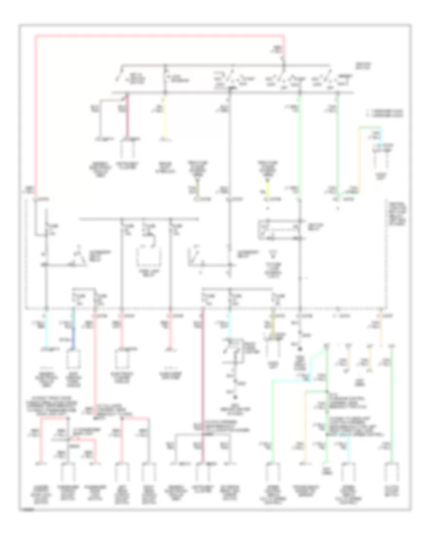
Power Distribution Wiring Diagram (1 of 3) for Ford Escape 2004

List of elements for Power Distribution Wiring Diagram (1 of 3) for Ford Escape 2004:
- (3.0l) (2.0l)
- (diagram 1 of 3)
- (in dash to headlamp junction harness, near breakout for daytime running lamps module)
- (in dash to headlamp red
- (in taillamps harness, near breakout to parking brake switch)
- (on left front corner of engine compt) battery junction box (bjb)
- 4 speaker audio
- 7 speaker audio
- A/c clutch relay
- Abs control module
- Abs test connector
- Audio unit
- Battery
- Battery junction box (bjb) (on left front corner of engine compt)
- Blower motor relay
- Brake pedal position switch
- C102a
- C1035a
- C1035c c1035b
- C201a
- C201b
- C220c
- C240a
- C270b
- C270d
- C270e
- C290
- Central junction box (cjb) (below left end of dash)
- Data link connector (dlc)
- Daytime running lamps (drl) module
- Daytime running lamps (drl) relay
- Deactivator switch
- Fog lamp relay
- Four- wheel drive relay
- From fuse 19 (bjb) (diagram 1 of 3)
- From headlamp relay (diagram 1 of 3)
- Front driver side heated seat module
- Front passenger side heated seat module
- Fuel pump relay
- Fuse 10a
- Fuse 15a
- Fuse 15a (if equipped)
- Fuse 20a
- Fuse 25a
- Fuse 30a
- Fuse 30a (3.0l)
- Fuse 40a
- Fuse 40a (2.0l)
- Fuse 50a (3.0l)
- Fuse 5a
- Fuse 60a
- Fuse b 120a
- G201 (behind center of dash)
- G403 (left rear end of vehicle)
- Generator
- Generic electronic module (gem)
- Headlamp relay
- High speed fan control relay 1
- Horn relay
- Instrument cluster
- Junction harness, near battery junction box)
- Left power seat switch
- Low speed fan control relay
- Medium speed fan control relay
- Near breakout to passive anti-theft transceiver) s216
- Pcm power relay
- Power point (behind center of dash)
- Powertrain control module (pcm)
- Rear power point (on left side of cargo compt)
- Rear window defrost relay
- Red
- S124
- S126
- S140
- S203
- S3002
- S414
- Starter motor
- Starter relay
- To accessory relay (diagram 2 of 3)
- To fuse 10 (bjb)
- To fuse 24 (bjb) (diagram 1 of 3)
- To ignition relay (diagram 2 of 3)
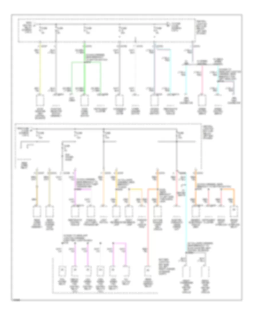
Power Distribution Wiring Diagram (2 of 3) for Ford Escape 2004
List of elements for Power Distribution Wiring Diagram (2 of 3) for Ford Escape 2004:
- (2.0l w/ speed control)
- (in main harness, near breakout to illumination dimmer) s220
- (in right front door window regulator wiring harness, near breakout to front passenger side door lock unit)
- (in taillamps harness, near breakout to g300) s310
- (not used)
- 4 speaker audio
- 7 speaker audio
- A/t
- Acc
- Accessory delay relay
- Accessory relay
- Audio unit
- Brake shift interlock
- Breakout for c134)
- C201a
- C2027b
- C220a
- C220c
- C240a
- C240a c290
- C270a
- C270b
- C270c
- C270d
- C270e
- C270f
- C290
- Central junction box (cjb) (below left end of dash)
- Clutch cutoff switch
- Electronic flasher module
- Exterior rear view mirror switch
- From fuse 19 (bjb) (diagram 1 of 3)
- From fuse 20 (bjb) (diagram 1 of 3)
- Front cigar lighter
- Fuse 10a
- Fuse 15a
- Fuse 20a
- Fuse 30a
- Fuse 5a
- G201 (behind center of dash)
- G300 (left front floor)
- Generic electronic module (gem)
- Ignition relay
- Ignition switch
- Instrument cluster
- Key in ignition switch
- Left rear window adjust switch
- Lock
- Lock solenoid
- M/t
- Master window/ door lock/ unlock switch
- Off
- Park lamp relay
- Passenger door lock switch
- Passenger window adjust switch
- Right rear window adjust switch
- Roof opening panel module
- Run
- S203
- S309
- S6000
- Speed control servo (2.0l w/ speed control)
- Speed control servo (3.0l w/ speed control)
- Start
- Subwoofer amplifier
- To fuse 1 (cjb) (diagram 3 of 3)
- Transmission range (tr) sensor
- W/ passenger door lock
Power Distribution Wiring Diagram (3 of 3) for Ford Escape 2004
List of elements for Power Distribution Wiring Diagram (3 of 3) for Ford Escape 2004:
- (2.0l)
- (3.0l)
- (in dash to headlamp junction harness, in battery junction box) s128
- (in main harness, near breakout to ignition switch) s215
- (in main harness, near breakout to ignition switch) s222
- (in taillamps harness, near breakout to evap canister vent control solenoid) s3003
- (not used)
- A/c clutch relay
- Abs test connector
- Air bag sliding contact
- Battery junction box (bjb) (on left front corner of engine compt)
- Brake shift interlock
- Brake shift interlock relay
- C201a
- C2041a
- C218a
- C220b
- C220c
- C270a
- C270b
- C270c
- C270d
- C270f
- C294a
- Central junction box (cjb) (below left end of dash)
- Daytime running lamps (drl) module
- Electro- chromatic inside mirror unit
- Evap canister vent control solenoid
- Four- wheel drive switch
- From fuse 5 (cjb) (diagram 3 of 3)
- From ignition d
- Front driver side
- Front passenger side heated seat module
- Function selector switch assembly
- Fuse 10a
- Fuse 20a
- Fuse 3a
- Fuse 5a
- Generic electronic module (gem)
- Heated seat module
- High speed fan control relay 1
- High speed fan control relay 2
- Instrument cluster
- Left reversing lamp
- Light switch
- Low speed fan control relay
- Medium speed fan control relay
- Parking aid module (pam)
- Passive anti-theft transceiver
- Pcm power diode
- Pcm power relay
- Rear window defrost relay
- Rear window washer pump motor
- Rear wiper motor assembly
- Rear wiper relay
- Relay (diagram 2 of 3)
- Restraints control module
- Right reversing lamp
- S1000 (near breakout to left side turn signal lamp)
- Speed control servo
- To fuse 3 (cjb) (diagram 3 of 3)
- W/ heated seats
- W/ abs
- W/ abs & speed control
- W/ speed control
- Windshield wiper motor
- Wiper/ washer switch