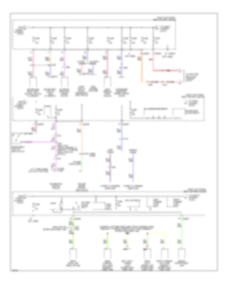
POWER DISTRIBUTION
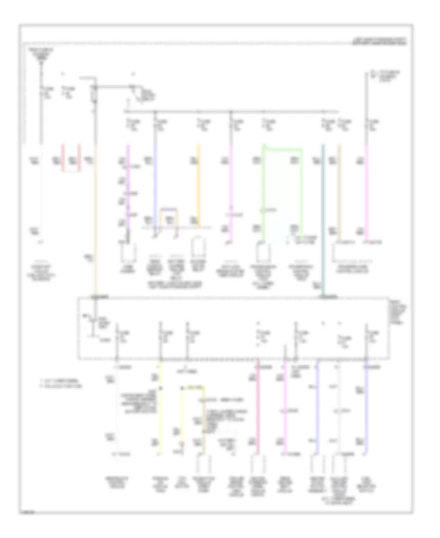
Power Distribution Wiring Diagram (1 of 9) for Ford F-450 Super Duty XLT 2014

List of elements for Power Distribution Wiring Diagram (1 of 9) for Ford F-450 Super Duty XLT 2014:
- (6.2l flex fuel & 6.8l) (6.7l turbo diesel)
- (6.7l turbo diesel: battery cable wiring assembly, in breakout to battery) (except 6.7l turbo diesel: alternator rectifier system wiring assembly, in breakout to battery)
- (alternator rectifier system wiring harness, near breakout to battery)
- (crew chief)
- (left side of engine compt) battery junction box (bjb)
- (right side of engine compt) high current battery junction box
- (w/ 10 way power seat)
- (w/ 6 way
- 6.7l turbo diesel w/ dual generators
- Auxiliary heater control module (ahcm) (6.7l turbo diesel w/ rapid heat)
- Battery
- Battery junction box (bjb) (left side of engine compt)
- Blower motor relay
- C1273a
- C1617a
- C1617b
- C1617c
- C1617d
- C1617e
- C1617f
- C210
- C2108
- C211
- C2463a
- C311
- C312
- C341a
- C555
- Crew chief
- Driver side front power window motor
- Driver side front seat control switch (w/o memory)
- Driver's seat module (dsm) (w/ memory)
- Front wiper relay
- Fuse 25a
- Fuse 30a
- Fuse 40a
- Fuse 40a 50a
- Fusible link b (20 ga- red) (right front of engine, in battery wiring assembly)
- Fusible link c (12 ga- red) (right front of engine, in battery wiring assembly)
- Fusible link d (12 ga- red) (right front of engine, in battery wiring assembly)
- Generator
- Glow plug control module (6.7l turbo diesel)
- Inline fuse (right end of dash)
- Mega fuse 125a
- Mega fuse 175a 275a
- Mega fuse 200a
- Nca
- Parking lamp trailer tow relay
- Passenger side front seat control switch
- Power seat)
- Rear window defrost relay
- Red
- Reductant heater relay (6.7l turbo diesel)
- S137
- S138
- S139
- S140 (alternator rectifier system wiring harness, near breakout to c144)
- S141 (alternator rectifier system wiring harness, between fusible link b & c)
- S272 (t-box jumper wiring harness, near breakout to c2108)
- Secondary battery (6.7l)
- Secondary generator
- Starter motor
- Telematics module
- To body control module (diagram 5 of 9)
- To fuse 39 (diagram 2 of 9)
- Trailer brake control (tbc) module
- W/ rear heated power sliding window
- W/o rear heated power sliding window
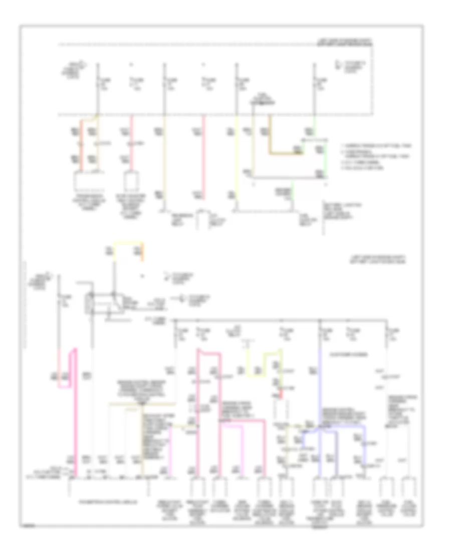
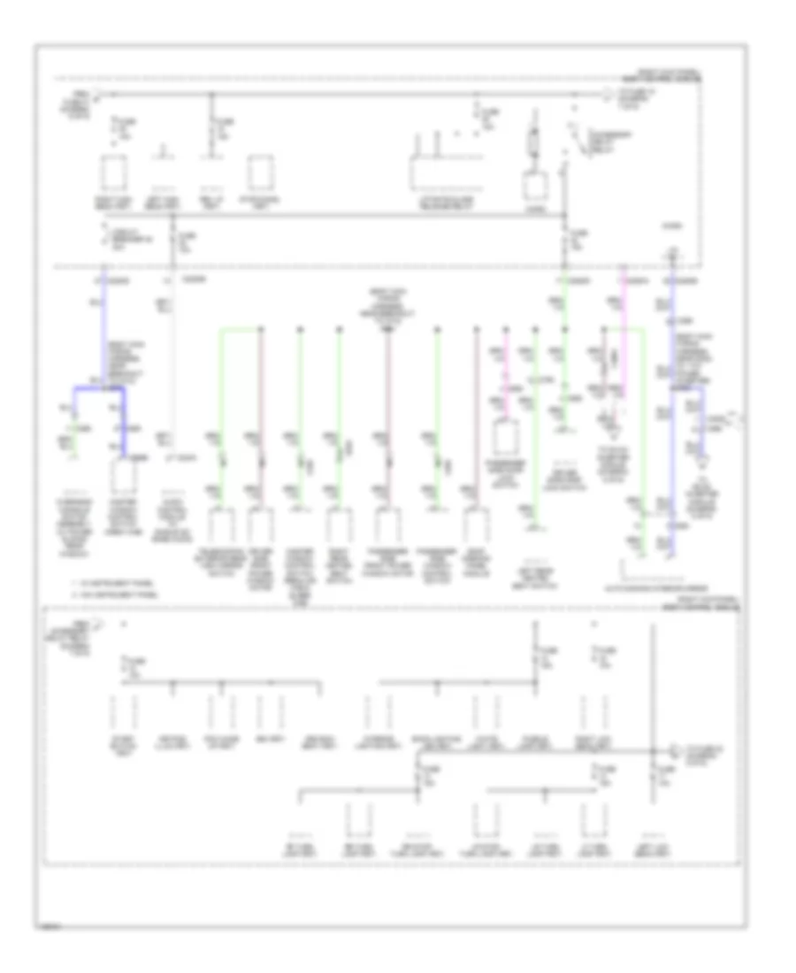
Power Distribution Wiring Diagram (2 of 9) for Ford F-450 Super Duty XLT 2014
List of elements for Power Distribution Wiring Diagram (2 of 9) for Ford F-450 Super Duty XLT 2014:
- (crew chief)
- (left side of engine compt) battery junction box (bjb)
- (not used)
- (t-box jumper wiring harness, near breakout to c2108) (crew chief) s274
- 6.7l turbo diesel
- 6.8l & 6.2l flex fuel
- Anti-lock brake system (abs) module
- Auxiliary heater control module (ahcm) (6.7l turbo diesel w/ rapid heat)
- Battery charge trailer tow relay
- Battery junction box (bjb) (left side of engine compt)
- Blower motor relay
- Body control module (right kick panel)
- C1010
- C1232b
- C1415
- C1581
- C175b
- C2108
- C214
- C2280b
- C2280d
- C2280e
- C2280f
- C2371a
- C2371b
- C2463b
- C3049
- C310a
- C3162b
- C465
- C497
- Center stack switch assembly
- Constant vacuum hub lock (cvh) solenoid
- From fuse 23 (diagram 1 of 9)
- Fuel tank selector switch
- Fuse 10a
- Fuse 15a
- Fuse 20a
- Fuse 5a
- Fuse 7.5a
- Heated steering wheel module (hswm)
- Micro
- Nca
- Parking aid module (pam)
- Powertrain control module (pcm)
- Rear heated seat module
- Rear window defrost relay
- Restraints control module
- Run/ start (fet)
- Run/ start relay
- S227 (instrument panel wiring harness, near breakout to inertia fuel shutoff switch)
- Telematics module (crew chief)
- To fuse 46 (diagram 3 of 9)
- Tow haul switch
- Trailer brake control (tbc) module
- Transfer case control module
- Transmission control module (tcm) (6.7l turbo diesel)
- Video camera
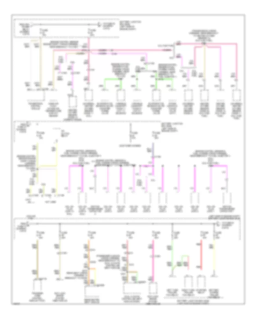
Power Distribution Wiring Diagram (3 of 9) for Ford F-450 Super Duty XLT 2014
List of elements for Power Distribution Wiring Diagram (3 of 9) for Ford F-450 Super Duty XLT 2014:
- (customer access)
- (engine control sensor engine compt wiring harness, in breakout to powertrain control module) s105
- (engine control sensor engine compt wiring harness, near breakout to c1581) s122
- (engine wiring harness, near breakout to fuel injector 1) s110
- (engine wiring harness, near breakout to intake throttle actuator) s109
- (left side of engine compt) battery junction box (bjb)
- (not used)
- 6.7l turbo diesel
- 6.8l & 6.2l flex fuel
- A/c clutch relay
- Battery junction box (bjb) (left side of engine compt)
- C1010
- C1047
- C110
- C1165
- C1232b
- C1273c
- C139
- C1415
- C1581
- C175b
- C3047
- C3611a
- C3619a
- Cooling fan
- Egr cooler bypass valve solenoid
- Evap canister vent control solenoid (except 6.7l turbo diesel)
- From c fuse 40 (diagram 2 of 9)
- From d fuse 68 (diagram 3 of 9)
- Fuel pressure control valve
- Fuel pump (fp) motor diode
- Fuel pump (fp) relay
- Fuel volume control valve
- Fuse 10a
- Fuse 15a
- Fuse 20a
- Fuse n/a
- Glow plug control module
- Mass air flow/ intake air temperature (maf/iat) sensor
- Narrow frame w/o aft fuel tank
- Nca
- Nox 11 sensor module (except high sulfur)
- Nox 12 sensor module (except high sulfur)
- Pcm power relay
- Powertrain control module
- Red
- Reductant pump assembly (except high sulfur)
- Reductant purge valve (except high sulfur)
- Reversing lamp relay
- S3000
- To fuse 33 (diagram 4 of 9)
- To fuse 72 (diagram 3 of 9)
- To fuse 84 (diagram 4 of 9)
- Transmission control module (6.7l turbo diesel)
- Turbo- charger actuator
- Turbo- charger wastegate regulating valve solenoid
- Wide frame & narrow frame w/ aft fuel tank
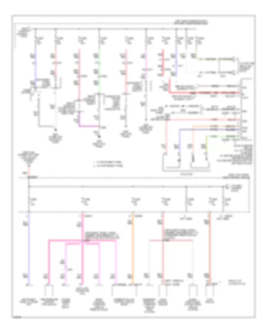
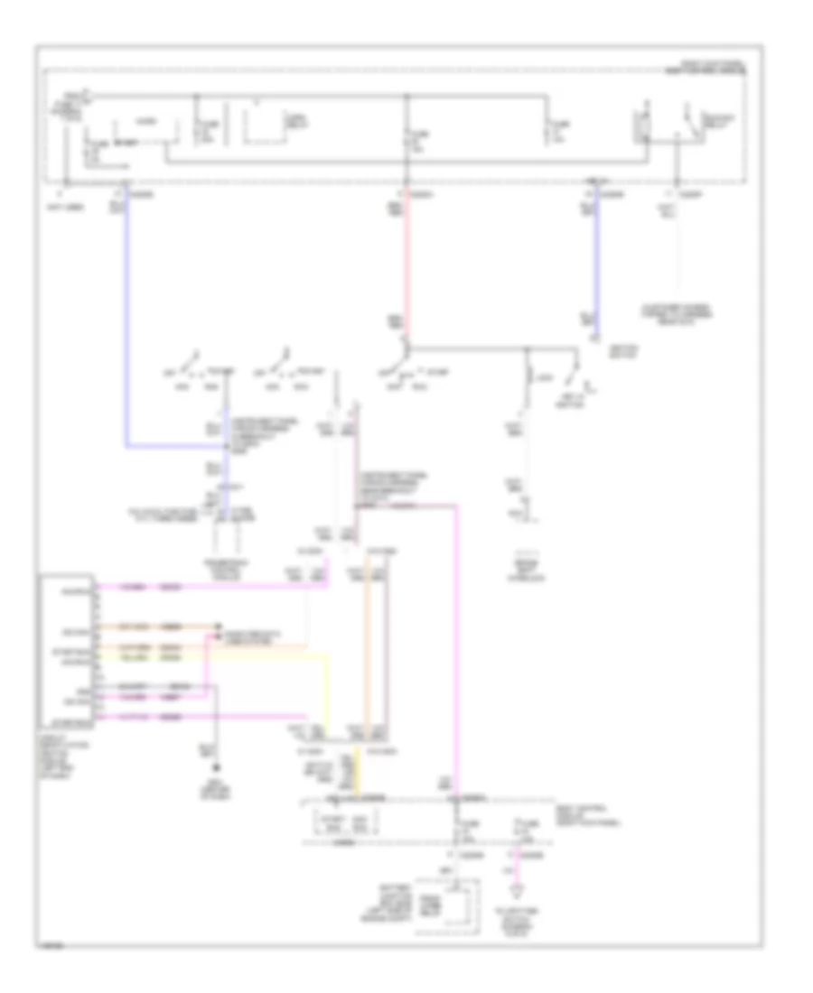
Power Distribution Wiring Diagram (4 of 9) for Ford F-450 Super Duty XLT 2014
List of elements for Power Distribution Wiring Diagram (4 of 9) for Ford F-450 Super Duty XLT 2014:
- (customer access)
- (engine control sensor & fuel charge wiring harness, near breakout to c133) s117
- (engine control sensor & fuel charge wiring harness, near breakout to fuel injector 1) (6.8l) s127 (6.2l flex fuel) s118
- (engine control sensor & fuel charge wiring harness, near breakout to fuel injector 1) s112
- (engine control sensor & fuel charge wiring harness, near breakout to fuel injector 5)
- (engine control sensor & fuel charge wiring harness, near breakout to fuel injector 7) (6.8l) s135 (6.2l flex fuel) s114
- (engine control sensor engine compt wiring harness, near breakout to c1581)
- (engine control sensor engine compt wiring harness, near breakout to horn) s101
- (left side of engine compt) battery junction box (bjb)
- (not used)
- (passenger cushion wiring harness, near breakout to dual climate controlled seat module)
- (transmission wiring harness, near breakout to heated oxygen sensor 12) (6.2l flex fuel) s181
- 6.2l flex fuel
- 6.8l
- A/c clutch relay
- Anti-lock brake system (abs) module
- Battery charge trailer tow relay
- Battery junction box (bjb) (left side of engine compt)
- C1168
- C1220
- C145
- C1581
- C175b
- C210
- C2371b
- C312
- C3162b
- C3265a e
- Coil on plug (cop) 1
- Coil on plug (cop) 10 (6.8l)
- Coil on plug (cop) 2
- Coil on plug (cop) 3
- Coil on plug (cop) 4
- Coil on plug (cop) 5
- Coil on plug (cop) 6
- Coil on plug (cop) 7
- Coil on plug (cop) 8
- Coil on plug (cop) 9 (6.8l)
- Cooling fan
- Dual climate controlled seat module (dcsm)
- Evaporative emission (evap) canister purge valve
- From e fuse 72 (diagram 3 of 9)
- From g fuse 34 (diagram 4 of 9)
- From pcm f power relay (diagram 3 of 9)
- Fuse 10a
- Fuse 15a
- Fuse 20a
- Fuse 25a
- Fuse 30a
- Fuse 40a
- Fuse 50a
- Fuse n/a
- Heated oxygen sensor (ho2s) 12 (6.2l flex fuel)
- Heated oxygen sensor (ho2s) 12 (narrow frame)
- Heated oxygen sensor (ho2s) 22 (6.2l flex fuel)
- Ignition transformer capacitor
- Ignition transformer capacitor 1
- Intake manifold tuning valve (imtv)
- Left turn trailer tow relay
- Mass air flow/ intake air temperature (maf/iat) sensor
- Nca
- Not used
- Powertrain control module
- Rear heated seat module
- Red
- Right turn trailer tow relay
- S104
- S315 (rear seat wiring harness, in breakout to c3049)
- S341
- Starter relay
- To fuse 35 (diagram 4 of 9)
- To fuse 83 (diagram 5 of 9)
- Transfer case control module (tccm)
- Universal heated oxygen sensor (ho2s) 11 (6.2l flex fuel)
- Universal heated oxygen sensor (ho2s) 11 (6.8l)
- Universal heated oxygen sensor (ho2s) 21
- Variable camshaft timing 11 (vct 11) solenoid
- Variable camshaft timing 21 (vct 21) solenoid
Power Distribution Wiring Diagram (5 of 9) for Ford F-450 Super Duty XLT 2014
List of elements for Power Distribution Wiring Diagram (5 of 9) for Ford F-450 Super Duty XLT 2014:
- (base)
- (instrument panel wiring harness, near breakout to inertia fuel shutoff switch) s228
- (instrument panel wiring harness, near breakout to passenger airbag module) (w/ sync) s222
- (left side of engine compt) battery junction box (bjb)
- (not used)
- (or sbb99)
- (premium)
- (right kick panel) body control module
- Ac outlet
- Ac-a
- Ac-b
- Acc
- Accessory protocol interface module (apim) (w/ sync)
- Audio control module
- Automatic a/c
- C210
- C211
- C215
- C2280a
- C2280b
- C2280g
- C228a
- C2293a
- C2293b
- C238
- C240a
- C2414a
- C2414b
- C290a
- C3052
- C3501a
- C3501b
- Cbp32
- Cigar lighter
- Consolette power point (crew cab w/ consolette)
- Data link connector (dlc)
- Dc/ac inverter module (w/ 110v power inverter) (w/ center console: under center console) (w/o center console: bottom left end of dash)
- From h fuse 90 (diagram 4 of 9)
- From high current battery junction box (diagram 1 of 9)
- From splice s314 l (diagram 7 of 9)
- From splice s383 m (diagram 7 of 9)
- Front console power point (super cab & crew cab)
- Front control interface module (premium audio)
- Fuse 10a
- Fuse 15a
- Fuse 20a
- Fuse 25a
- Fuse 40a
- Fuse 5a
- G203 (lower left center of dash)
- G300 (left kick panel)
- G302 (right kick panel)
- Gd179 (or gd115)
- Global positioning system (gpsm) module (w/ sync)
- Gnd
- Hot
- Hvac module
- Hya01
- Hya02
- Instrument panel cluster (ipc)
- Instrument panel power point 1
- Instrument panel power point 2
- Led+
- Led-
- Lin 01
- Lya03
- Manual a/c
- Neut
- Power mirror fold relay
- Rear console power point
- Red
- Rya03
- S390
- Sbb97
- Steering column control module (sccm)
- Tire pressure monitor (tpm) module
- To fuse 7 (diagram 6 of 9)
- To upfitter relay box (diagram 9 of 9)
- Vdn01
- W/ instrument panel
- W/o instrument panel
Power Distribution Wiring Diagram (6 of 9) for Ford F-450 Super Duty XLT 2014
List of elements for Power Distribution Wiring Diagram (6 of 9) for Ford F-450 Super Duty XLT 2014:
- (crew chief)
- (interior lamp feed headliner wiring harness, near breakout to rear interior & map lamps assembly) (super cab & crew cab) s908
- (not used)
- (right kick panel) body control module
- (taped to harness near c422)
- (taped to harness near c465)
- 6.7l turbo diesel 6.8l & 6.2l flex fuel
- All lock/unlock relay
- Audio digital signal processing (dsp) module
- Battery saver relay
- Brake pedal position (bpp) switch
- C1232b
- C1415
- C175b
- C210
- C2108
- C212
- C215
- C2280b
- C2280d
- C2280f
- C248 c268
- C265
- C300
- C3154c
- C341b
- C465
- C555
- C655
- Driver door unlock relay
- Driver seat module (dsm) (w/ memory)
- Driver side front seat control switch (w/ memory)
- Engine compartment lamp
- Exterior rearview mirror switch
- Fog lamp relay
- From n fuse 27 (diagram 5 of 9)
- From o fuse 9 (diagram 6 of 9)
- From r fuse 20 (diagram 6 of 9)
- Front dome lamp (regular cab)
- Front interior/ map lamps assembly (super cab & crew cab)
- Fuse 10a
- Fuse 15a
- Fuse 20a
- Fuse 30a
- Fuse 5a
- Fuse 7.5a
- Left corner lamp (fet)
- Left vanity mirror lamp (super cab & crew cab)
- Micro
- Narrow frame
- Park lamp relay
- Passenger side front power window motor
- Powertrain control module
- Rear interior/ map lamps assembly (crew cab)
- Red
- Regular cab
- Right corner lamp (fet)
- Right vanity mirror lamp (super cab & crew cab)
- Roof opening panel module
- S207 (body main wiring harness, in breakout to brake pedal position switch)
- Sub- woofer amplifier
- Super cab & crew cab
- To fuse 21 (diagram 6 of 9)
- To fuse 39 (diagram 7 of 9)
- To fuse 4 (diagram 6 of 9)
- To upfitter relay box (diagram 9 of 9)
- Trailer brake control (tbc) module
- W/ sony sound
- W/o sony sound
- Wide frame
Power Distribution Wiring Diagram (7 of 9) for Ford F-450 Super Duty XLT 2014
List of elements for Power Distribution Wiring Diagram (7 of 9) for Ford F-450 Super Duty XLT 2014:
- (body main wiring harness, near breakout to c312) s314
- (body main wiring harness, near breakout to c312) s371
- (right kick panel) body control module
- 3rd row seat (fet)
- Accessory delay relay
- Audio control module (w/ single cd/ base audio)
- Auto dimming interior mirror
- Back-lighting led (fet)
- Bsi (fet)
- C2280a
- C2280b
- C2280d
- C240a
- C264
- C265
- C268
- C3052
- C555
- C566b
- C655
- C755
- C855
- Circuit breaker 48 30a
- Driver side door lock switch
- Driver side front power window motor
- From s fuse 47 (diagram 6 of 9)
- From t accessory delay relay (diagram 7 of 9)
- Fuse 10a
- Fuse 15a
- Interior lighting (fet)
- Keypad illum (fet)
- Left high beam (fet)
- Left low beam (fet)
- Left rear heated seat switch
- Lf turn lamp (fet)
- Liftgate glass release relay
- Lin
- Lr stop/ turn lamp (fet)
- Lr turn lamp (fet)
- Master window control switch (crew cab)
- Master window control switch (regular cab & super cab)
- Micro
- Overhead console switch assembly (w/ power sliding rear window)
- Passenger side door lock switch
- Passenger side front power window motor
- Passenger side window control switch
- Pcm wake up (fet)
- Puddle lamp (fet)
- Rev lp (fet)
- Rf turn lamp (fet)
- Right high beam (fet)
- Right low beam (fet)
- Right rear heated seat switch
- Roof opening panel module
- Rr stop/ turn lamp (fet)
- Rr turn lamp (fet)
- Start button (fet)
- Stop/chmsl (fet)
- Telescoping exterior rear view mirror switch
- To dc/ac inverter module (diagram 5 of 9)
- To fuse 18 (diagram 7 of 9)
- To fuse 22 (diagram 8 of 9)
- W/ instrument panel
- W/o instrument panel
- White light (fet)
Power Distribution Wiring Diagram (8 of 9) for Ford F-450 Super Duty XLT 2014
List of elements for Power Distribution Wiring Diagram (8 of 9) for Ford F-450 Super Duty XLT 2014:
- (customer access tapped to harness near c210)
- (instrument panel wiring harness, in breakout to g203) s285
- (instrument panel wiring harness, near breakout to c213) s284
- (not used)
- (right kick panel) body control module
- 6.8l & 6.2l flex fuel 6.7l turbo diesel
- Acc
- Acc/ run
- Acc/run
- Battery junction box (bjb) (left side of engine compt)
- Body control module (right kick panel)
- Brake shift interlock
- C1232b
- C175b
- C211
- C2280a
- C2280b
- C2280e
- C2280f
- Cdc33
- Cdc34
- Cdc62
- Cdc63
- Circuit deactivation ignition module (left end of dash)
- Computer data lines system
- From u fuse 17 (diagram 7 of 9)
- Front wiper relay
- Fuse 10a
- Fuse 15a
- Fuse 20a
- Fuse 5a
- G201 (center of dash)
- Gd184
- Gnd
- Horn relay
- Ignition switch
- Key in
- Key in ignition
- Lock
- Micro
- Ms can+
- Ms can-
- Nca
- Off
- Powertrain control module
- Run
- Run/acc relay
- Start
- Start/ run
- Start/run
- To upfitter switch (diagram 9 of 9)
- Vdb06
- Vdb07
- W/ cdim
- W/o cdim
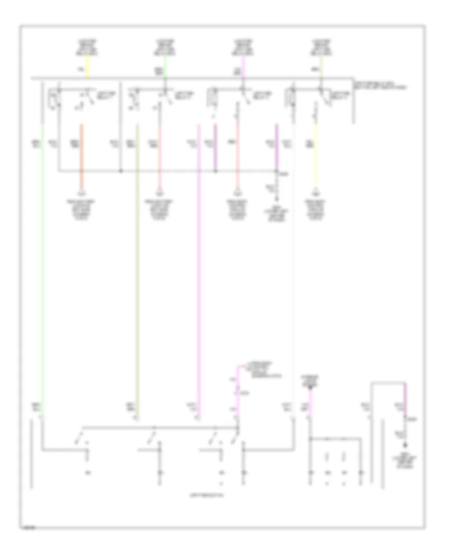
Power Distribution Wiring Diagram (9 of 9) for Ford F-450 Super Duty XLT 2014
List of elements for Power Distribution Wiring Diagram (9 of 9) for Ford F-450 Super Duty XLT 2014:
- (located behind upfitter relay box)
- C215
- From battery junction box (bjb) (diagram 5 of 9)
- From body control module (diagram 6 of 9)
- From body control module (diagram 8 of 9)
- G204 (lower left center of dash)
- Interior lights system
- Red
- S249
- Upfitter relay 1
- Upfitter relay 2
- Upfitter relay 3
- Upfitter relay 4
- Upfitter relay box (bottom left end of dash)
- Upfitter switch