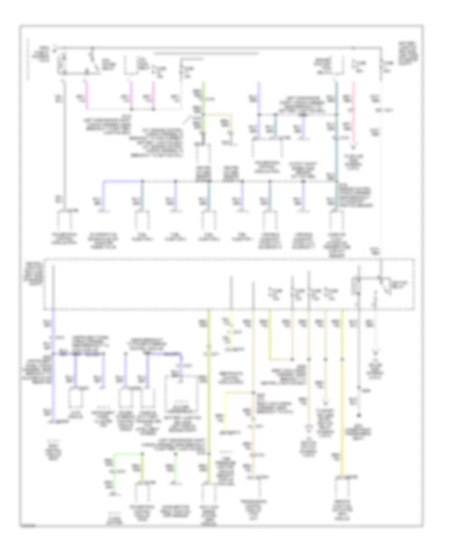
POWER DISTRIBUTION
Power Distribution Wiring Diagram (1 of 5) for Ford Fiesta S 2011

List of elements for Power Distribution Wiring Diagram (1 of 5) for Ford Fiesta S 2011:
- (engine control wiring harness, in breakout to transmission control module) s100
- (not used)
- A/c clutch relay
- A/t
- Anti-lock brake system (abs) module
- Battery
- Battery junction box (bjb) (left side of engine compt)
- Blower motor relay
- Body control module (bcm)
- C1100a
- C133
- C1617a
- C1617b
- C1617c
- C1750a
- C175b
- C210
- C211
- C2280a
- C2368a
- C504a
- Coil pack relay
- Daytime running lamps (drl) relay
- Engine cooling fan relay
- Exterior rear view mirror switch (early production)
- From fuse 11 (diagram 1 of 5)
- Fuse 10a
- Fuse 15a
- Fuse 20a
- Fuse 30a
- Fuse 40a
- Fuse 50a
- Fuse 7.5a
- Generator
- High beam relay
- High current battery junction box (bjb) (at battery)
- Low beam relay
- M/t
- Master window control switch (early production)
- Mega fuse 1 450a
- Mega fuse 2 60a
- Mega fuse 3 200a
- Mega fuse 4 70a
- Mega fuse 5 50a
- Natural vacuum leak detection module (nvldm)
- Power steering control module (pscm)
- Powertrain control module (pcm)
- Red
- Starter inhibit relay
- Starter motor
- To fuse 4 (diagram 1 of 5)
- To pcm power relay (diagram 2 of 5)
- Transmission control module (tcm) (a/t)
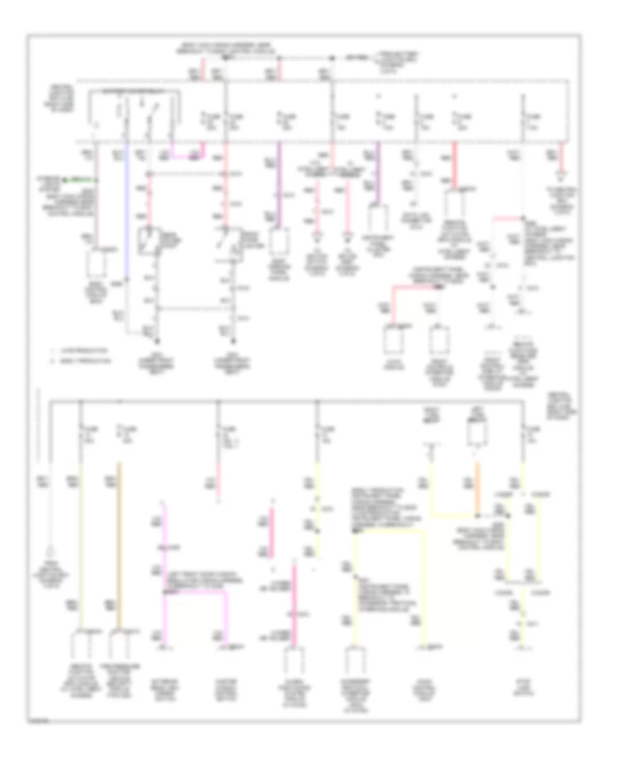
Power Distribution Wiring Diagram (2 of 5) for Ford Fiesta S 2011
List of elements for Power Distribution Wiring Diagram (2 of 5) for Ford Fiesta S 2011:
- (left side engine compt wiring harness, near breakout to battery junction box) s118
- (left side engine compt wiring harness, near breakout to battery junction box) s122
- (m/t: engine control wiring harness, in breakout to high current battery junction box) (a/t: engine control wiring harness, in breakout to ignition coil)
- (near breakout to power steering control module) s213
- Accelerator pedal position (app) sensor
- Anti-lock brake system (abs) module
- Battery junction box (bjb) (left side of engine compt)
- Blower motor relay
- Body control module (bcm)
- C133
- C1750a
- C175b
- C210
- C211
- C212
- C2280b
- C228a
- C2368b
- C310a
- C3503b
- C4321a
- Central junction box (cjb) (left side of engine compt)
- Coil pack relay
- Engine cooling fan relay
- Evaporative emission (evap) canister purge valve
- Floor shifter
- From fuse 27 (diagram 1 of 5)
- Fuel injector 1
- Fuel injector 2
- Fuel injector 3
- Fuel injector 4
- Fuse 10a
- Fuse 15a
- Fuse 60a
- Fuse 7.5a
- G301 (under front passenger's seat)
- Heated oxygen sensor (ho2s) 11
- Heated oxygen sensor (ho2s) 12
- Hvac module
- Ignition relay
- Instrument panel cluster (ipc)
- Mass air flow/ intake air temperature (maf/iat) sensor
- Nca
- Output shaft speed (oss) sensor (m/t w/o abs)
- Passive anti-theft transceiver (w/o intelligent access)
- Pcm power relay
- Power steering control module (pscm)
- Powertrain control module (pcm)
- Remote function actuator (rfa) module
- Restraints control module (rcm)
- S102 (engine control wiring harness, near breakout to camshaft position sensor)
- S103
- S116 (left side engine compt wiring harness, near breakout to battery junction box)
- S228
- S239 (instrument panel wiring harness, near breakout to blower motor resistor)
- S256
- S257 (a/t) (body main wiring harness, near breakout to c214)
- S259 (body main wiring harness, near breakout to central junction box)
- Tire pressure monitor/ vehicle security module (tpm/vsm)
- To ignition switch (diagram 4 of 5)
- To smart keyless entry ignition relay (diagram 4 of 5)
- To splice s252 (diagram 3 of 5)
- To splice s255 (diagram 5 of 5)
- Transmission control module (tcm) (a/t)
- Variable camshaft timing (vct) solenoid 11
- Variable camshaft timing (vct) solenoid 12
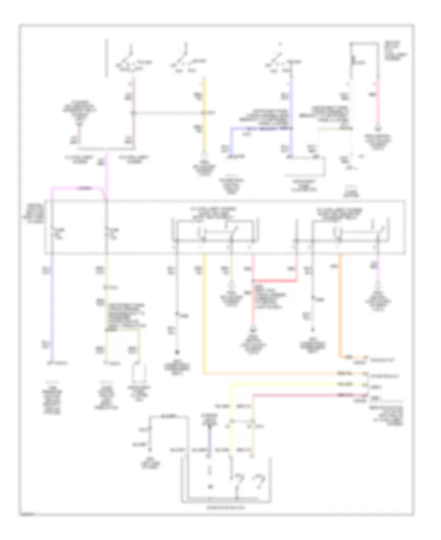
Power Distribution Wiring Diagram (3 of 5) for Ford Fiesta S 2011
List of elements for Power Distribution Wiring Diagram (3 of 5) for Ford Fiesta S 2011:
- (body main wiring harness, near breakout to body control module) s252
- (body main wiring harness, near breakout to central junction box)
- (early production: instrument panel wiring harness, near breakout to g202) (late production: instrument panel wiring harness, in breakout) s226
- (instrument panel wiring harness, near breakout to g202) s225
- 4 door
- 5 door
- Accessory protocol interface module (apim) (w/ sync)
- Audio control module (acm)
- Battery saver relay
- Body control module (bcm)
- C211
- C212
- C213
- C2280c
- C228a
- C240a
- C314
- C315
- C339 a8
- C3503a
- C4321a
- C504a
- Central junction box (cjb) (right side of dash)
- Data link connector (dlc)
- Early production
- Exterior rear view mirror switch
- From battery junction box c (diagram 2 of 5)
- From central junction box (diagram 3 of 5)
- Front cigar lighter
- Front control/ display interface module (fcdim)
- Front controls interface module (fcim)
- Fuse 10a
- Fuse 15a
- Fuse 15a 7.5a
- Fuse 20a
- Fuse 7.5a
- G301 (under front passenger's seat)
- Global positioning system module (w/ sync)
- Hvac module
- Instrument panel cluster (ipc)
- Interior lights system
- Late production
- Left turn relay
- Master window control switch
- Rear power point
- Red
- Remote function actuator (rfa) module (w/ intelligent access)
- Remote functions receiver (rfr) module (w/ intelligent access)
- Right turn relay
- Roof opening panel module
- S201 (instrument panel wiring harness, in breakout to accessory protocol interface module)
- S248 (body main wiring harness near breakout to body control module)
- S250 (body main wiring harness, near breakout to body control module)
- S256
- Stop lamp switch
- Tire pressure monitor/ vehicle security module (tpm/vsm)
- To central junction box (diagram 3 of 5)
- To ignition switch (diagram 4 of 5)
- To splice s253 (diagram 4 of 5)
- W/ intelligent access
- W/o intelligent access
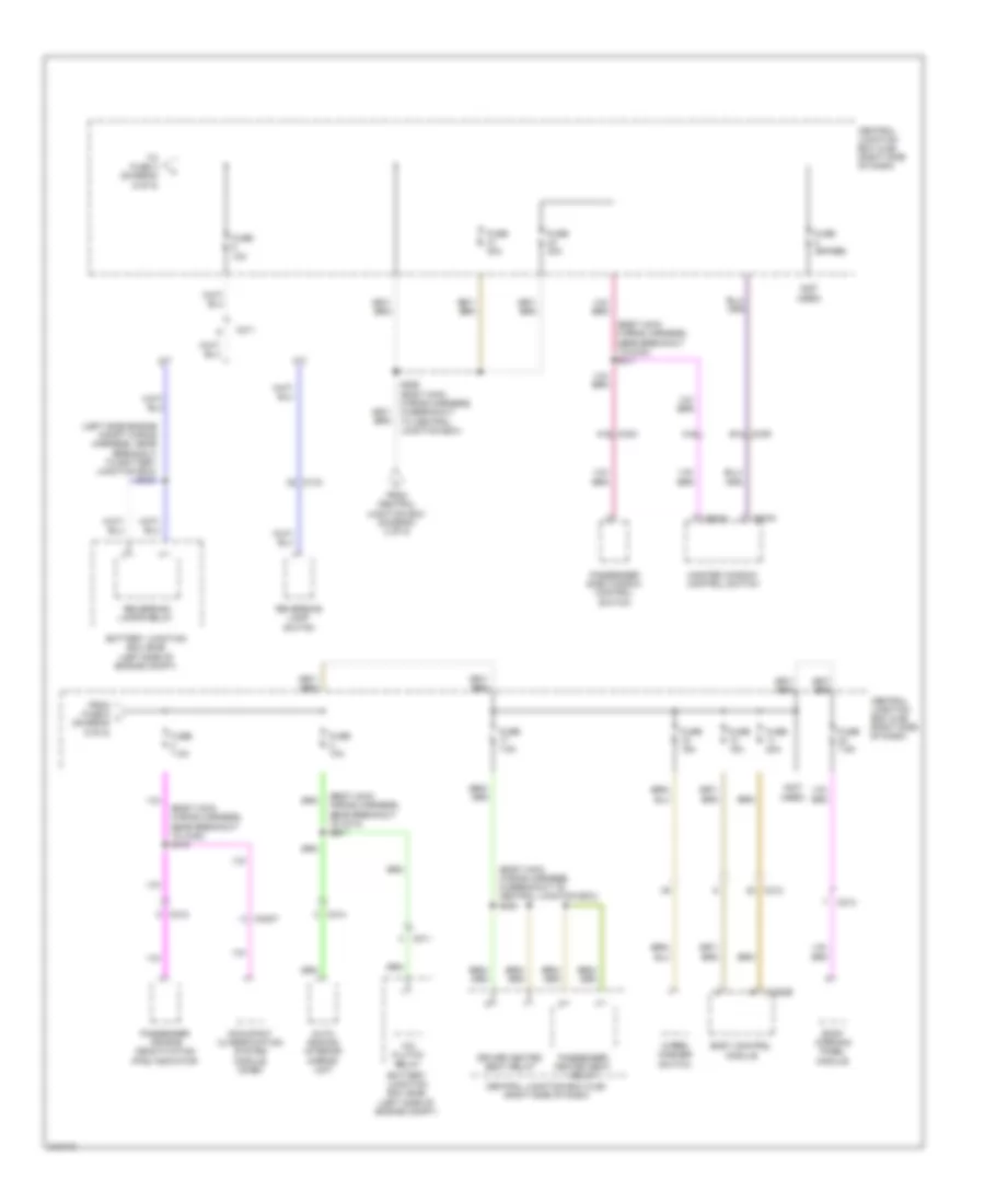
Power Distribution Wiring Diagram (4 of 5) for Ford Fiesta S 2011
List of elements for Power Distribution Wiring Diagram (4 of 5) for Ford Fiesta S 2011:
- (instrument panel wiring harness, in breakout to instrument panel cluster) (a/t) s219
- (instrument panel wiring harness, near breakout to instrument panel cluster) s230
- (w/ intelligent access) smart keyless entry accessory relay
- (w/ intelligent access) smart keyless entry ignition relay
- A/t
- Acc
- Audio control module (acm) (early production)
- C175b
- C210
- C212
- C240a
- C3503b
- C3503c
- C4321a
- Central junction box (cjb) (right side of dash)
- Floor shifter
- From central junction box (diagram 3 of 5)
- From central junction box (diagram 4 of 5)
- From splice s259 (diagram 2 of 5)
- Fuse 7.5a
- G201 (left side of dash)
- G301 (under front passenger's seat)
- Ignition switch (w/o intelligent access)
- Instrument panel cluster (ipc)
- Interior lights system
- Lock
- Off
- Powertrain control module (pcm)
- Red
- Remote function actuator (rfa) module (w/ intelligent access)
- Run
- Run/acc out
- S218
- S253 (body main red wiring harness, in breakout to central junction box)
- S256
- Ssb 1
- Ssb 2
- Start
- Start/run out
- Start/stop switch
- Sw 1
- Sw 2
- Tire pressure monitor/ vehicle security module (tpm/vsm)
- To smart keyless entry accessory relay (diagram 4 of 5)
- W/ intelligent access
- W/o intelligent access
Power Distribution Wiring Diagram (5 of 5) for Ford Fiesta S 2011
List of elements for Power Distribution Wiring Diagram (5 of 5) for Ford Fiesta S 2011:
- (body main wiring harness, in breakout to central junction box) s254
- (body main wiring harness, near breakout to c214) s261
- (body main wiring harness, near breakout to c340) s310
- (body main wiring harness, near breakout to c340) s311
- (left side engine compt wiring harness, near breakout to battery junction box) s121
- (not used)
- A/c clutch relay
- A/t
- A15
- Auto dimming interior mirror unit
- Battery junction box (bjb) (left side of engine compt)
- Body control module
- C133
- C211
- C212
- C213
- C214
- C2280b
- C3007
- C339 b14
- C340 a15
- C504a
- C504c
- Central junction box (cjb) (right side of dash)
- Driver heated seat relay
- From central junction box (diagram 2 of 5)
- From fuse 6 l (diagram 5 of 5)
- Fuse (spare)
- Fuse 10a
- Fuse 15a
- Fuse 20a
- Fuse 30a
- Fuse 7.5a
- M/t
- Master window control switch
- Occupant classification system module (ocsm)
- Passenger air bag deactivation (pad) indicator
- Passenger heated seat relay
- Passenger side window control switch
- Reversing lamp switch
- Reversing lamps relay
- Roof opening panel module
- S255 (body main wiring harness, in breakout to central junction box)
- To fuse 4 (diagram 5 of 5)
- Wiper/ washer switch