POWER DISTRIBUTION
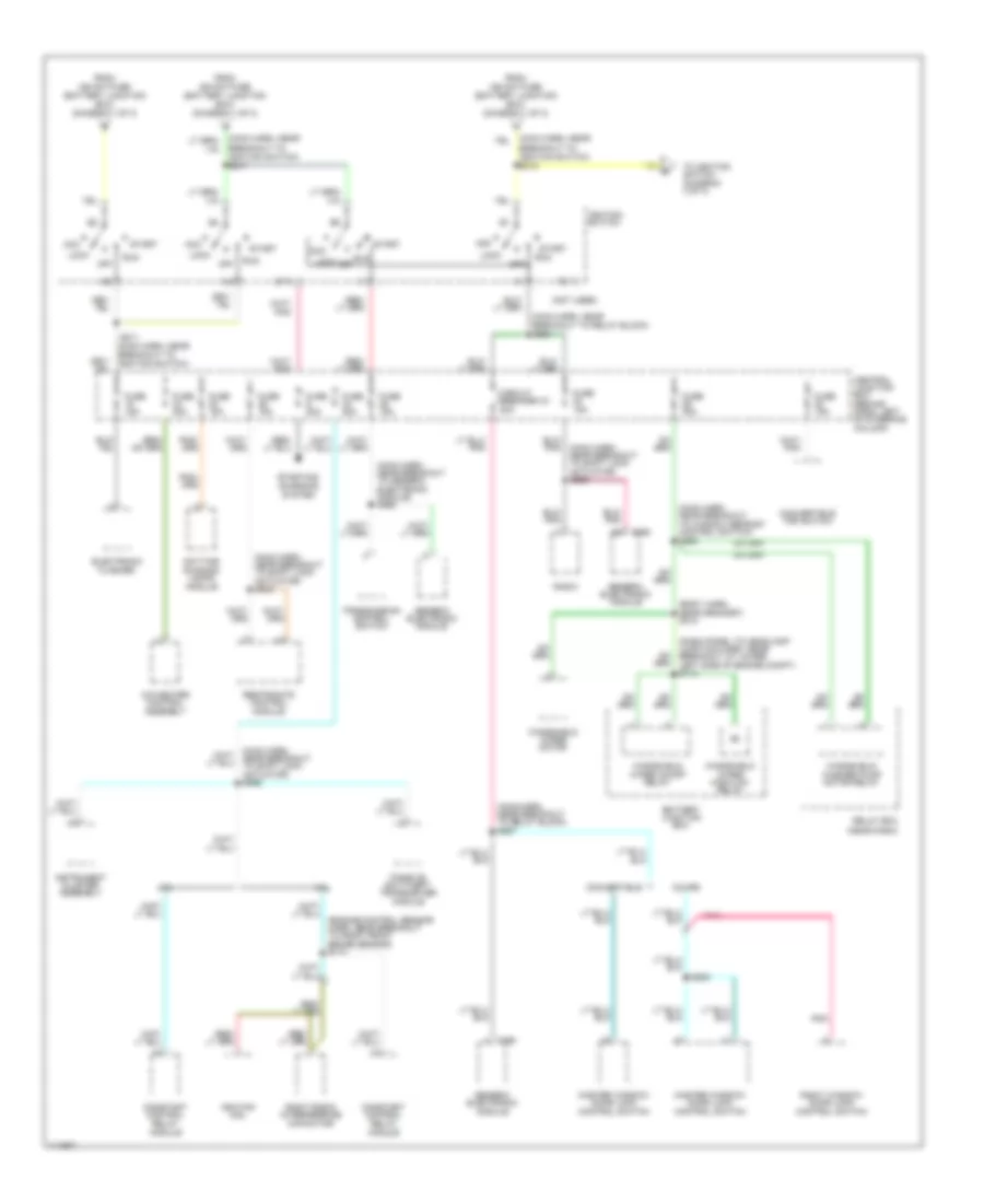
Power Distribution Wiring Diagram (1 of 3) for Ford Mustang Cobra 2000

List of elements for Power Distribution Wiring Diagram (1 of 3) for Ford Mustang Cobra 2000:
- (1999)
- (1999-00)
- (2000)
- (body harn, near breakout to conv lower relay) s409
- (body harn, near breakout to generic electronic module) s269
- (dash panel to headlamp junction harn, in breakout to battery junction block)
- (eng cntrl sens harn, right side of engine compt)
- (main harn, below rear of center console) s273
- (main harn, left side of dash) s236
- (main harn, near breakout to rear window defrost control switch) s233
- (main harn, near breakout to rear window defrost control switch) s242
- (main harn, near breakout to restraints control module) s270
- (main harness, left rear engine compt) s260
- 3.8l
- 3.8l (1999)
- 30a
- 4.6l
- 4.6l 3.8l
- A/c pressure fuse 20a
- Abs fuse 20a
- Abs fuse 50a
- Air injection reaction relay
- Alt fuse 20a
- Anti-lock brake control module
- Audio fuse 10a
- Auxiliary power socket
- Battery
- Battery junction box (in left side of engine compt, forward of strut tower)
- C280
- C281
- C290
- C291
- Cd player
- Central junction box (behind dash, left of steering column)
- Cigar lighter
- Constant control relay module
- Conv top circuit breaker 25a
- Data link connector
- Daytime running lights module
- Driver's seat control switch
- Electronic flasher
- Exterior rear view mirror switch
- Fan circuit breaker 30a
- Fan fuse 50a
- Fog lamps relay
- Fog, drl fuse 20a
- Fuel pump fuse 20a
- Fuse 10a
- Fuse 15a
- Fuse 20a
- Fuse 25a
- G300 (below rear of center console)
- Generator
- Generic electronic module
- Hd lps fuse 30a
- Horn fuse 20a
- Horn relay
- Htd bl fuse 30a
- Ign sw fuse 40a
- Int i/p fuse 40a
- Lower relay
- Luggage compt lid relay
- Luggage compt lid release switch
- Main light switch
- Master window/ door lock control switch
- Multi- function switch
- Nca
- Park lamp relay
- Park lamps fuse 30a
- Pcm power fuse 30a
- Power point fuse 20a
- Power seat fuse 25a
- Power windows fuse 40a
- Radio
- Raise relay
- Rear window defrost control switch
- Red
- Relay box (near dash)
- Right window/ door lock control switch
- S102
- S108
- S109 (dash panel to headlamp junction harn, lower left side of eng compt)
- S111
- S303
- S303 (console panel harn, near breakout to auxiliary power socket)
- S504 (left door/ window regulator harn, near breakout to left door speaker)
- Starter motor/ solenoid
- Starter relay
- Therm fuse 30a
- To fuse 27 (diagram 3 of 3)
- To ignition switch (diagram 2 of 3)
- To splice s215 (diagram 2 of 3)
- To splice s217 (diagram 2 of 3)
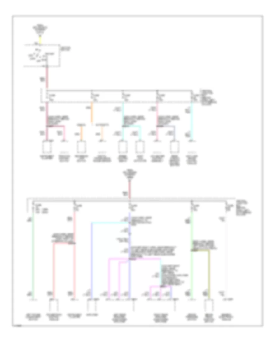
Power Distribution Wiring Diagram (2 of 3) for Ford Mustang Cobra 2000
List of elements for Power Distribution Wiring Diagram (2 of 3) for Ford Mustang Cobra 2000:
- (body harn, near grommet) s312
- (dash panel to headlamp junction harn, near breakout at lower left side of engine compt) s113
- (engine control sensor harn, near breakout to right front brake sensor) s174
- (main harn, near breakout to generic electronic module) s262
- (main harn, near breakout to ignition switch) s215
- (main harn, near breakout to ignition switch) s217
- (main harn, near breakout to relay block) s264
- (main harn, near breakout to relay block) s267
- (main harn, near breakout to shift lock actuator) s243
- (main harn, near breakout to shift lock actuator) s265
- (main harn, near breakout to shift lock actuator) s266
- (main harn, near breakout to window defrost control switch) s225
- (not used)
- 3.8l
- 4.6l
- A/c-heater control assembly
- Acc
- Battery junction box
- C290
- C352
- Central junction box (behind dash, left of steering column)
- Circuit breaker 43 20a
- Constant control relay module
- Convertible
- Convertible top switch
- Coupe
- Daytime running lamps module
- Electronic flasher
- From ign sw fuse (battery junction box) (diagram 1 of 3)
- Fuse 15a
- Fuse 20a
- Fuse 30a
- Generic electronic module
- Ignition coil
- Ignition switch
- Instrument cluster assembly
- Lock
- Master window/ door lock control switch
- Off
- Passive anti-theft transceiver module
- Pnk
- Radio
- Relay box (near dash)
- Restraints control module
- Right radio interference capacitor
- Right window/ door lock control switch
- Run
- S211 (main harn, near breakout to ignition switch)
- S505
- Sta
- Start
- Starting/ charging system
- To ignition switch (diagram 3 of 3)
- Transmission control switch
- Windshield washer pump motor relay
- Windshield wiper high/low relay
- Windshield wiper motor
- Windshield wiper on/off relay
Power Distribution Wiring Diagram (3 of 3) for Ford Mustang Cobra 2000
List of elements for Power Distribution Wiring Diagram (3 of 3) for Ford Mustang Cobra 2000:
- (1999) (2000)
- (body harn, near breakout behind left side of dash, near clutch pedal) s207
- (convert-body harn, near breakout to left rear subwoofer amplifier, coupe-radio amplifier harn, near breakout to left rear subwoofer amplifier) s432
- (main harn, near breakout behind dash, right of steering column) s259
- (main harn, near breakout behind right side of dash) s245
- (main harn, near breakout behind right side of dash) s256
- (main harn, near breakout behind right side of dash) s257
- (main harn, near breakout to ignition switch) s258
- A/c heater control assembly
- Acc
- Amplifier
- Anti-lock brake control module
- Automatic
- Brake pedal position switch
- Brake pressure switch
- C251
- C282
- C291
- C408
- C409
- Central junction box (behind dash, left of steering column)
- Digital transmission range sensor
- From splice s215 (diagram 2 of 3)
- From splice s260 (diagram 1 of 3)
- Fuse 15a
- Fuse 20a 15a
- Fuse 25a
- Fuse 5a
- Generic electronic module
- Ignition switch
- Instrument cluster
- Left power lumbar seat switch
- Left rear speaker subwoofer amplifier
- Lock
- Manual
- Off
- Powertrain control module
- Rear window defrost control switch
- Reversing lamp switch
- Right rear speaker subwoofer amplifier
- Run
- Shift lock actuator
- Speed control servo
- Start
- Traction control switch