POWER DISTRIBUTION
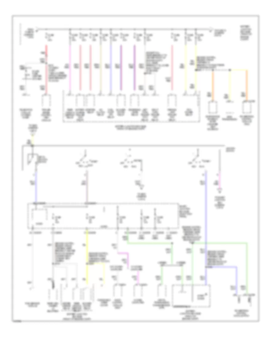
Power Distribution Wiring Diagram (1 of 5) for Ford Pickup F150 2010

List of elements for Power Distribution Wiring Diagram (1 of 5) for Ford Pickup F150 2010:
- (12 ga- red)
- (alternator rectifier system wiring harness, in breakout to fusible link c) s143
- (body main wiring harness, near breakout to g300) s309
- (engine control sensor wiring harness, near breakout to c146) s109
- (engine control sensor wiring harness, near breakout to c146) s110
- (front of engine compt) battery junction box (bjb)
- (not used)
- (passenger seat wiring harness, in breakout to passenger's seats) s341
- (super/super crew cab: near breakout to c313) s324
- 3rd row seat enable (fet)
- Anti-lock brake system (abs) module
- Audio digital signal processing (dsp) module
- Battery
- Brake pedal position (bpp) switch
- Bsi (fet)
- C2280d (not used)
- C2280g
- C2371b
- C3313b
- C341a
- C341b
- C341c
- Console 1 power point (w/ column shifter)
- Console 1 power point (w/ floor shifter)
- Console 2 power point (w/ floor shifter)
- Driver seat module (dsm)
- Driver side front seat control switch
- Dual climate controlled seat module (if equipped)
- Exterior rear view mirror switch
- Floor lamp (fet)
- From battery (diagram 1 of 5)
- Front cigar lighter
- Fuse 10a
- Fuse 15a
- Fuse 20a
- Fuse 30a
- Fuse 60a
- Fuse 7.5a
- Fusible link a
- Fusible link b (12 ga- red)
- Fusible link d
- Fusible link e
- G201 (right kick panel)
- G203 (left side of dash)
- Generator
- Heated seat module (if equipped)
- In breakout to fusible link e)
- Instrument panel power point
- Integrated wheel end (iwe) solenoid
- Interior lighting (fet)
- Key pad illum (fet)
- Micro
- Passenger side front seat control switch
- Power running board (prb) module
- Red
- S142 (alternator rectifier system wiring harness, red
- S144 (alternator rectifier system wiring harness, in breakout to fusible link c)
- S329
- Smart junction box (sjb) (right kick panel)
- Starter motor
- To fuse 17 (diagram 2 of 5)
- To fuse 17 (diagram 3 of 5)
- To s110 (diagram 1 of 5)
- Tpms 1 (fet)
- Tpms 2 (fet)
- Tpms 3 (fet)
- Transfer case control module (tccm)
- Transfer case control module (tccm) (w/ esof)
- W/ memory
- W/o memory
- Windshield wiper motor
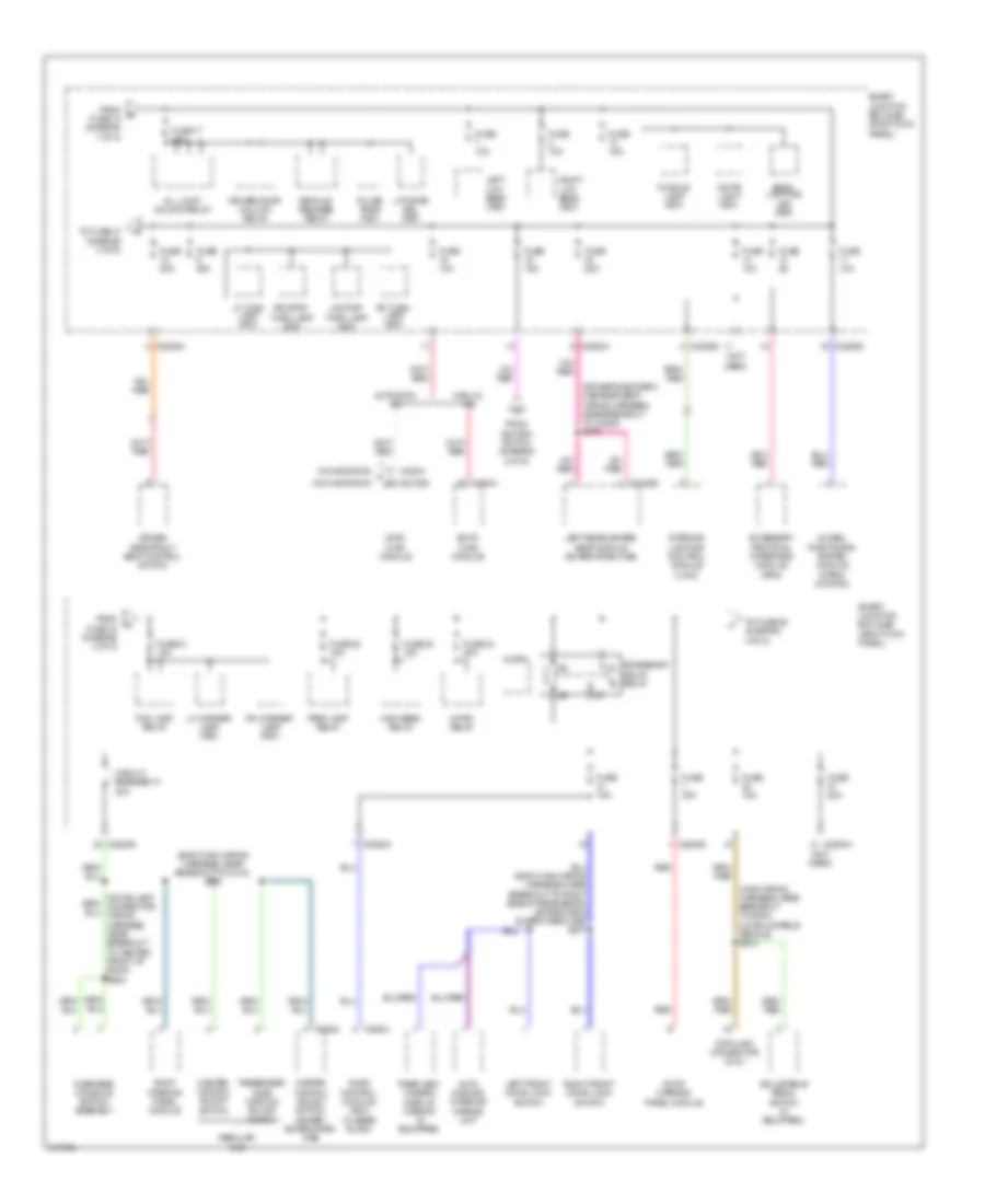
Power Distribution Wiring Diagram (2 of 5) for Ford Pickup F150 2010
List of elements for Power Distribution Wiring Diagram (2 of 5) for Ford Pickup F150 2010:
- (engine control sensor wiring harness, near breakout center front of engine compartment) (w/ rear view camera) s133
- (engine control sensor wiring harness, near breakout to c214) s200
- (engine control sensor wiring harness, near breakout to center front of engine compt) s123
- (engine control sensor wiring harness, near breakout to center front of engine compt) s128
- (except 5.4l: near breakout to center front of engine compt) (5.4l: near breakout to lower right front of engine) s122
- (not used)
- 4 speed a/t
- 6 speed a/t
- 6r80 transmission
- A/c clutch relay
- Acc
- Audio control module (acm)
- Battery charge trailer tow relay
- Battery junction box (bjb) (front of engine compt)
- Blower motor relay
- C175b
- C2280a
- C2280b
- C2280d
- C2280e
- C2408a
- C290a
- Digital transmission range sensor (dtr)
- Evaporative emission (evap) canister vent solenoid
- From fuse 68 (diagram 1 of 5)
- Fuel pump (fp) relay
- Fuse 10a
- Fuse 20a
- Fuse 30a
- Fuse 40a
- Fuse 5a
- Heated mirror relay
- Ignition switch
- In dash computer
- Inline fuse (center of dash)
- Key in ignition switch
- Left turn trailer tow relay
- Micro
- Nca
- Off
- Parking lamp trailer tow relay
- Pcm power relay
- Powertrain control module (pcm)
- Rain sensor module
- Rear view camera (if equipped)
- Rear window defrost relay
- Red
- Reversing lamps relay
- Right turn trailer tow relay
- Run
- S272 (w/ crew chief) (t-box jumper wiring harness, near breakout to c2108)
- Smart junction box (sjb) (right kick panel)
- Smrc
- Start
- Start diode
- Starter relay
- Telematics module (w/ crew chief)
- To fuse 18 (diagram 5 of 5)
- To s220 (diagram 4 of 5)
- To s230 (diagram 4 of 5)
- To smart junction box (diagram 3 of 5)
- Trailer brake control (tbc) module
- W/ in dash computer
- W/o in dash computer
- Windshield wiper motor
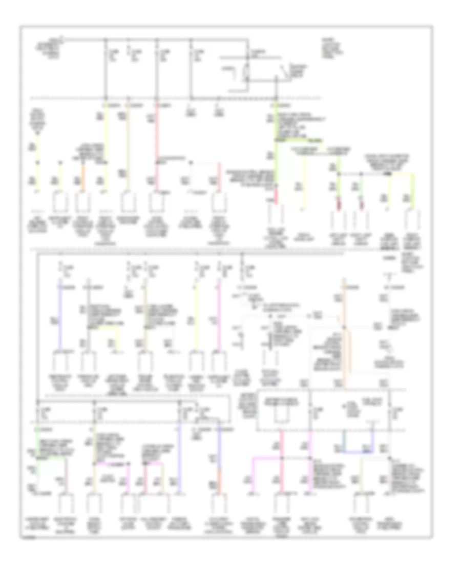
Power Distribution Wiring Diagram (3 of 5) for Ford Pickup F150 2010
List of elements for Power Distribution Wiring Diagram (3 of 5) for Ford Pickup F150 2010:
- (body main wiring harness, near breakout to c312) s313
- (driver side crew cab rear seat wiring harness, near breakout to c3205) s370
- (main wiring harness, near breakout to g203) (w/ adjustable pedals) s212
- (not used)
- Accessory delay relay
- Accessory protocal interface module (apim)
- Adjustable pedal switch (if equipped)
- All lock/ unlock relay
- Audio control module (acm) (w/ base audio)
- Auto dimming interior mirror unit
- Automatic a/c
- Back- lighting led (fet)
- C2109a
- C2280a
- C2280b
- C2280d
- C228a
- C290a
- C294a
- C3162b
- C535a
- Circuit breaker 47 30a
- Data link connector (dlc)
- Datc hvac module
- Decklid release relay
- Driver door unlock relay
- Driver side front seat control switch
- Emtc hvac module
- Fog lamp relay
- From fuse 12 (diagram 1 of 5)
- From fuse 18 (diagram 3 of 5)
- From ignition switch (diagram 2 of 5)
- Fuse 10a
- Fuse 15a
- Fuse 17 20a
- Fuse 20a
- Fuse 21 15a
- Fuse 22 15a
- Fuse 23 15a
- Fuse 24 20a
- Fuse 30a
- Fuse 5a
- Global positioning system module (gpsm) (w/ sync)
- High beam relay
- Horn relay
- Interior lighting control module (ilcm))
- Left front door lock switch
- Left low beam (fet)
- Left rear heated seat module (super crew cab)
- Lf turn lamp (fet)
- Lh corner lamp (fet)
- Liftgate rel (fet)
- Lr stop/ turn lamp (fet)
- Manual a/c
- Master window adjust switch
- Master window adjust switch (super/ super crew cab)
- Micro
- Overhead console switch assembly
- Park lamp relay
- Passenger side window adjust switch
- Puddle lamp (fet)
- Pulse train (fet)
- Rear view camera display mirror (if equipped)
- Red
- Regular cab
- Rf turn lamp (fet)
- Rh corner lamp (fet)
- Right front door lock switch
- Right low beam (fet)
- Roof opening panel module
- Rr stop/ turn lamp (fet)
- Smart junction box (sjb) (right kick panel)
- To fuse 21 (diagram 3 of 5)
- To fuse 26 (diagram 4 of 5)
- W/ navigation
- W/o navigation
- White light (fet)
Power Distribution Wiring Diagram (4 of 5) for Ford Pickup F150 2010
List of elements for Power Distribution Wiring Diagram (4 of 5) for Ford Pickup F150 2010:
- (console wiring harness, near breakout to c3007) s331
- (dome lamp connector wiring harness, near breakout to left front of roof) s901
- (engine control sensor wiring harness, near breakout to left rear of engine compt) s191
- (main wiring harness, near breakout to center of dash) s220
- (main wiring harness,near near breakout to c213) s230
- (not used)
- (w/ heated seats) s306
- (w/ navigation) s224
- 6r80 transmission (if equipped)
- Anti-lock brake system (abs) module
- Audio control module (acm) (w/o in dash computer)
- Battery charge trailer low relay
- Battery junction box (bjb) (front of engine compt)
- Battery saver relay
- Breakout to right side of dash) (w/ svt raptor) s233
- C175b
- C2280a
- C2280b
- C2280d
- C2280e
- C2371a
- C2408a
- C290a
- C310a
- Digital transmission range (dtr) sensor
- Electronic compass (if equipped)
- Floor shifter (w/ floor shifter)
- From ignition switch (diagram 2 of 5)
- From j accessory delay relay (diagram 3 of 5)
- Front controls interface module (fcim)
- Front display interface module (fdim) (w/ navigation)
- Front display interface module (fdim) (w/o navigation)
- Front dome lamp
- Front interior/ map lamp assembly
- Fuel pump (fp) relay
- Fuel pump motor diode
- Fuse 10a
- Fuse 20a
- Fuse 25 10a
- Fuse 25a
- Fuse 5a
- Fuse 7.5a
- Hall descent control switch
- Hazard/ pad/ traction switch
- Heated seat module (if equipped)
- In dash computer (if equipped)
- Instrument cluster (ic)
- Key release interlock actuator
- Left lamp vanity mirror
- Left rear heated seat module (super crew cab)
- Micro
- Mode select switch (mss)
- Nca
- Occupant classification system module (ocsm)
- Off road mode switch
- Parking aid module (pam)
- Passive anti-theft transceiver
- Powertrain control module (pcm)
- Rear interior/ map lamp assembly
- Red
- Restraints control module (rcm)
- Right lamp vanity mirror
- S113 (engine control sensor wiring harness, near breakout to center front engine compt)
- S117 (6 speed a/t) (engine control sensor wiring harness, near breakout to center front of engine compt)
- S118 (engine control sensor wiring harness, near breakout to center front of engine compt)
- S222 (main wiring harness, near breakout to right side of dash)
- Smart junction box (sjb) (right kick panel)
- Subwoofer amplifier
- Telematics module (w/ crew chief)
- To upfitter switch (diagram 5 of 5)
- Tool link reader (w/ tool link in dash computer)
- Tow haul switch (w/ column shifter)
- Trailer brake control (tbc) module
- Transfer case control module (tccm)
- W/ overhead console
- W/ svt raptor
- W/o overhead console
- Wiring harness, near breakout to c2108) (w/ crew chief) s274
- Wiring harness, near breakout to g300) (super crew cab) s332
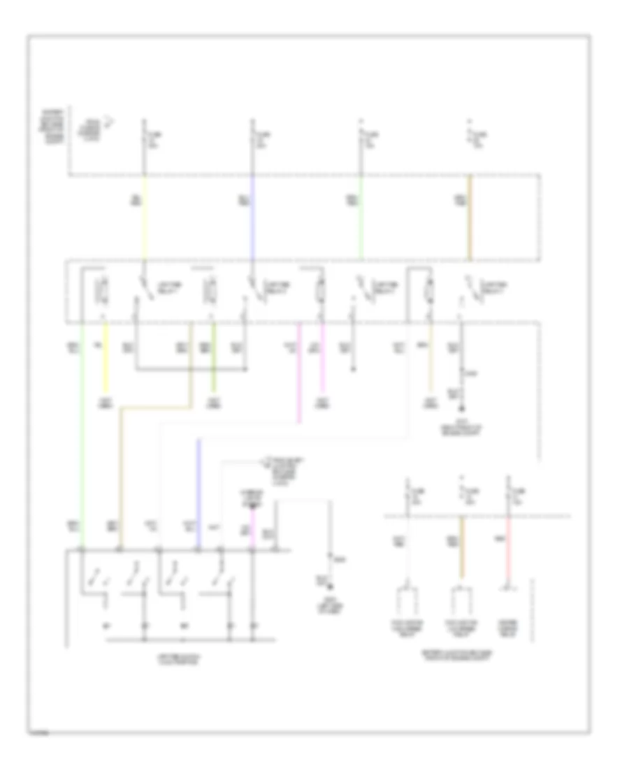
Power Distribution Wiring Diagram (5 of 5) for Ford Pickup F150 2010
List of elements for Power Distribution Wiring Diagram (5 of 5) for Ford Pickup F150 2010:
- (not used)
- Battery junction box (bjb) (front of engine compt)
- Cooling fan high speed relay
- Cooling fan low speed relay
- From fuse 26 (diagram 2 of 5)
- From smart junction box (sjb) (diagram 4 of 5)
- Fuse 10a
- Fuse 15a
- Fuse 30a
- Fuse 40a
- G101 (right front of engine compt)
- G203 (left side of dash)
- Heated mirror relay
- Interior lights system
- Red
- S106
- S329
- Upfitter relay 1
- Upfitter relay 2
- Upfitter relay 3
- Upfitter relay 4
- Upfitter switch (w/ svt raptor)