POWER DISTRIBUTION
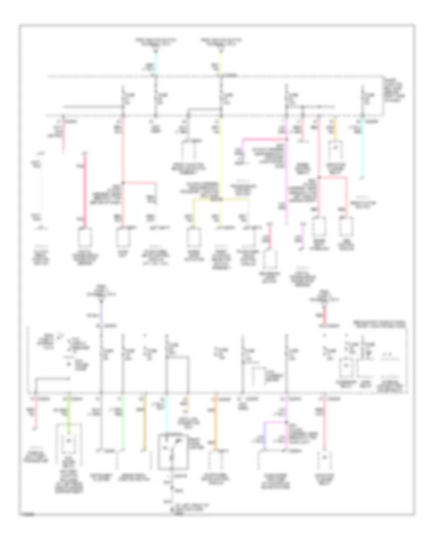
Power Distribution Wiring Diagram (1 of 2) for Ford Ranger 2004

List of elements for Power Distribution Wiring Diagram (1 of 2) for Ford Ranger 2004:
- (at left rear side of engine compartment) battery junction box (bjb)
- (behind right side of dash) smart junction box (sjb)
- (in dash to headlight junction harness, near breakout for p93) s127
- (in radio speaker jumper harness, at breakout for c314) s301
- (not used)
- A/c clutch relay
- Abs control module
- Acc
- Accessory relay
- Audio unit
- Battery
- Battery junction box (bjb) (at left rear side of engine compartment)
- Battery junction box (bjb) (at left rear side of engine compt)
- Blower motor relay
- C102a
- C220b
- C2280a
- C2280b
- C2280c
- C281a
- C281b
- C290a
- C3154a
- Door lock/ unlock relay
- Driver door unlock relay
- Drl driver
- Engine cooling fan relay
- Exterior rear view mirror switch
- Fog lamp relay
- Four- wheel drive control module
- Four-wheel drive control module
- Fuel pump relay
- Fuse 10a
- Fuse 15a
- Fuse 20a
- Fuse 20a (2.3l)
- Fuse 30a
- Fuse 40a
- Fuse 50a
- Fuse 5a
- G205 (at left front of vehicle floor)
- Generator
- Ignition switch
- Instrument cluster
- Lock
- Low current board
- Main light switch
- Multi-function switch
- Off
- Park lamp relay
- Passenger air bag deactivation (pad) switch
- Pcm power relay
- Power point
- Powertrain control module (pcm)
- Radio amplifier (tremor)
- Red
- Restraints control module
- Run
- S130 (in battery cable assembly, at breakout for fusible link a)
- S131 (in battery cable assembly, at breakout for fusible link b)
- S201 (in main harness, near breakout for center of dash)
- S203
- S223 (in main harness, near breakout for left side of dash)
- S228 (in main harness, near breakout for ignition switch)
- Smart junction box (sjb) (behind right side of dash)
- Sta
- Start
- Starter motor
- Starter relay
- To fuse 17 (diagram 2 of 2)
- To fuse 22 (diagram 2 of 2)
- To fuse 27 (diagram 2 of 2)
- To fuse 33 (diagram 2 of 2)
- To ptc circuit breaker (diagram 2 of 2)
- Windshield washer relay
- Windshield wiper motor
- Wiper high/low relay
- Wiper run/park relay
Power Distribution Wiring Diagram (2 of 2) for Ford Ranger 2004
List of elements for Power Distribution Wiring Diagram (2 of 2) for Ford Ranger 2004:
- (at left front of vehicle floor) g205
- (behind right side of dash) smart junction box (sjb)
- (in main harness, near breakout for smart junction box (sjb)) s216
- (not used)
- A/t
- Abs control module
- Accessory relay
- Audio unit
- Battery junction box (bjb) (at left rear side of engine compartment)
- Blend door actuator
- Brake pedal position switch
- Brake shift interlock
- C2031a
- C2031b
- C220b
- C2280a
- C2280b
- C2280c
- C2280d
- C281a
- C290a
- C294a
- C2982a
- Clutch pedal position switch
- Data link connector (dlc)
- Deactivator switch
- Digital transmission range (dtr) sensor
- Four-wheel drive control module
- Four-wheel drive control module (m/t, 3.0l, 4.0l)
- From fuse 3 (diagram 1 of 2)
- From fuse 5 (diagram 1 of 2)
- From fuse 10 (diagram 1 of 2)
- From ignition switch (diagram 1 of 2)
- Front cigar lighter
- Front function selector switch assembly
- Fuse 10a
- Fuse 15a
- Fuse 20a
- Fuse 2a
- Fuse 30a
- Fuse 5a
- Horn relay
- Indicator flasher relay
- Instrument cluster
- Interior lamp/battery saver relay
- Low current board
- M/t
- Nca
- Off
- Passive anti-theft transceiver
- Pcm power diode
- Pcm power relay
- Pnk
- Ptc circuit breaker 1a
- Red
- Reversing lamps switch
- S200 (in main harness, near breakout for center of dash)
- S203
- S221 (in main harness, near breakout for left side of engine compt)
- S231 (in main harness, near breakout for audio unit)
- S237 (in main harness, near breakout for smart junction box (sjb))
- Smart junction box (sjb) (behind right side of dash)
- Speed control servo
- Subwoofer amplifier (w/ audiophile sound system)
- Transmission control switch