RADIO
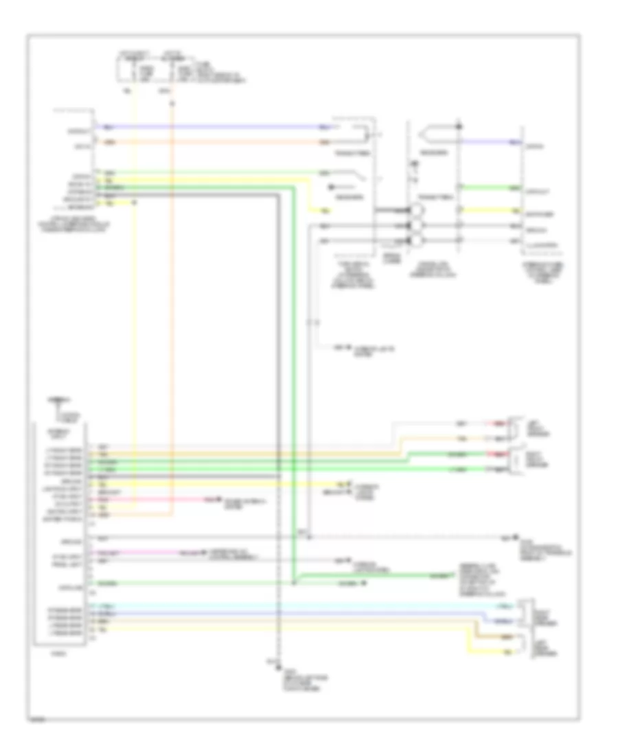
Radio Wiring Diagrams, with Amplifier for Oldsmobile Cutlass Supreme 1991

List of elements for Radio Wiring Diagrams, with Amplifier for Oldsmobile Cutlass Supreme 1991:
- 8v output
- Acc b+ in
- Amplifier (behind left side of i/p, left of steering column)
- Amplifier gain control
- Antenna
- Antenna input
- Assembly line diagnostic link j
- Bat
- Bat power
- Battery pwr in
- Cancel cam (inside top of steering column)
- Coaxial cable
- Connector (on bottom of i/p, right of steering column)
- Data bus
- Data in
- Data line
- Data out
- Elec fuse 15a
- Foglight/audio switch assembly
- Fuse block (right side of i/p, in i/p compartment)
- G129 (on engine stud, front of transaxle assembly)
- G202 (behind left side of i/p, near turn flasher)
- Gain input
- Ground
- Ground in
- Heater and a/c control assembly
- Hot at all times
- Hot in accy or run
- Htr-a/c and radio control interface module (inside steering column)
- Ignition input
- Illumination
- Indicator on
- Interior lights system
- Left front door speaker (1992-93)
- Left front speaker
- Left rear speaker
- Lights on input
- Lt front input
- Lt front spkr
- Lt rear input
- Lt rear input
- Lt rear spkr
- Mute input
- Nca
- On output
- Panel light
- Pnk
- Power antenna system
- Radio
- Radio fuse 10a
- Radio on input
- Receivers
- Red
- Right front door speaker (1992-93)
- Right front speaker
- Right rear speaker
- Rt front input
- Rt front spkr
- Rt rear input
- Rt rear spkr
- Spring loaded
- Steering wheel control head (in steering wheel)
- Tan
- Transmitters
- Turn signal switch (in steering column, below steering wheel)
- Vcc +5
- Vf dim input
- Woofer output
Radio Wiring Diagrams, without Amplifier for Oldsmobile Cutlass Supreme 1991
List of elements for Radio Wiring Diagrams, without Amplifier for Oldsmobile Cutlass Supreme 1991:
- Acc b+ in
- Antenna
- Antenna input
- Assembly line diagnostic link j
- Bat
- Bat power
- Battery pwr in
- Cancel cam (inside top of steering column)
- Coaxial cable
- Connector (on bottom of i/p, right of steering column)
- Data bus
- Data in
- Data line
- Data out
- Elec fuse 15a
- Fuse block (right side of i/p, in i/p compartment)
- G129 (on engine stud, front of transaxle assembly)
- G202 (behind left side of i/p, near turn flasher)
- Ground
- Ground in
- Ground
- Heater and a/c control assembly
- Hot at all times
- Hot in accy or run
- Htr-a/c and radio control interface module (inside steering column)
- Ignition input
- Illumination
- Interior lights system
- Left front speaker
- Left rear speaker
- Lights on input
- Lt front spkr
- Lt rear spkr
- Nca
- On output
- Panel light
- Pnk
- Power antenna system
- Radio
- Radio fuse 10a
- Receivers
- Red
- Right front speaker
- Right rear speaker
- Rt front spkr
- Rt rear spkr
- Spring loaded
- Steering wheel control head (in steering wheel)
- Tan
- Transmitters
- Turn signal switch (in steering column, below steering wheel)
- Vcc +5
- Vf dim input