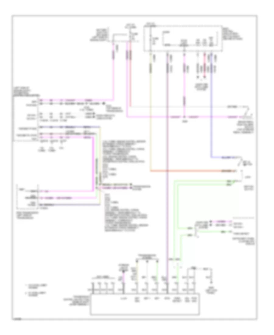
SHIFT INTERLOCK
Shift Interlock Wiring Diagram for Ford Escape SE 2014
List of elements for Shift Interlock Wiring Diagram for Ford Escape SE 2014:
- (1.6l turbo: engine control sensor extension wiring assembly, near breakout to g104) (2.0l turbo: engine control wiring assembly, in breakout to 6f35 transmission) (2.5l: engine control wiring assembly, near breakout to powertrain control module (pcm)) (2.5l) s102 (2.0l turbo) s104 (1.6l turbo) s130
- (left side of engine compt) powertrain control module (pcm)
- (not used)
- 1.6l turbo
- 2.0l turbo
- 2.5l
- 6f35 transmission (left side of transmission)
- Access
- Battery junction box (bjb) (left side of engine compt)
- Body control module (bcm) (bottom right center of dash)
- Bpp
- Brake pedal position (bpp) switch (top of brake pedal assembly)
- Btsi
- C1035c
- C1381b
- C1381e
- C1520a
- C1551b
- C1551e
- C175b
- C175t
- C2280a
- C2280c
- C2280f
- Ccb08
- Cdc30
- Cet53
- Computer data lines system
- Fuse 5a
- G104 (top rear of transmission)
- G205 (left kick panel)
- Gd120
- Hot at all times
- Hs can +
- Hs can -
- Ignition switch
- Illum
- Instrument panel cluster (ipc) module
- Interior lights system
- Key in ign sw
- Key in ignition
- Le111 (or let57)
- Lock
- Micro
- Ms can (+)
- Ms can (-)
- Ms can +
- Ms can -
- Nca
- Oss/ tr gnd
- Oss/ tr vpwr
- Park detect
- Pwr gnd
- Ret24
- S101 (2.5l) s106 (2.0l turbo) s132 (1.6l turbo) (2.5l: engine control wiring assembly, near breakout to powertrain control module (pcm)) (2.0l turbo: engine control wiring assembly, in breakout to 6f35 transmission) (1.6l turbo: engine control sensor extension wiring assembly, near breakout to c1019)
- S125 (1.6l turbo)
- S221
- S250
- Sol gnd
- Sst +
- Sst -
- Sst gnd
- Stop light switch
- Tr-p
- Transmission control switch (tcs) (base of shift lever assembly)
- Transmissions system
- Trs
- Tss/oss/tr gnd
- Tss/oss/tr vpwr
- Vdb04
- Vdb05
- Vdb06
- Vdb07
- Vet32
- W/ intelligent
- W/o intelligent
 English