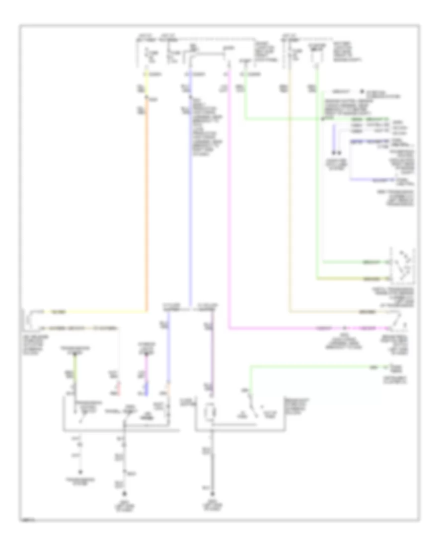
SHIFT INTERLOCK
Shift Interlock Wiring Diagram for Ford Pickup F250 Super Duty 2009
List of elements for Shift Interlock Wiring Diagram for Ford Pickup F250 Super Duty 2009:
- (engine control sensor wiring harness, near breakout to center front of engine compt) s123
- 6r80 transmission (6 speed a/t) (left rear of transmission)
- Battery junction box (bjb) (front of engine compt)
- Brake pedal position (bpp) switch (left side of dash)
- Brake shift interlock (steering column)
- Bsi (fet)
- C175b
- C2280a
- C2280b
- C2280c
- Ce336
- Cet39
- Computer data lines system
- Digital transmission range (dtr) sensor (4 speed a/t) (left side of transmission)
- Floor shifter
- Fuse 10a
- Fuse 15a
- G202 (left side of dash)
- G203 (left side of dash)
- Hot at all times
- Hs can+
- Hs can-
- In park
- Instrument cluster (ic)
- Interior lights system
- Key release interlock actuator (steering column)
- Led panel
- Micro
- Neutral
- Out of park
- Park
- Park detect
- Park neutral
- Park sens
- Powertrain control module (pcm) (right rear of engine compt)
- Range
- Red
- S220
- S231 (early production: main wiring harness, near breakout to c213) (late production: main wiring harness, near breakout to right side of dash)
- S232 (main wiring harness, near breakout to c238)
- S329
- Shift lock
- Smart junction box (sjb) (right kick panel)
- Smrc
- Start
- Starter relay
- Starting/ charging system
- Transmission control switch
- Transmissions system
- Vdb04
- Vdb05
- W/ column shifter
- W/ floor shifter
 English