SUPPLEMENTAL RESTRAINTS
Supplemental Restraint Wiring Diagram for Ford Cutaway E350 1998
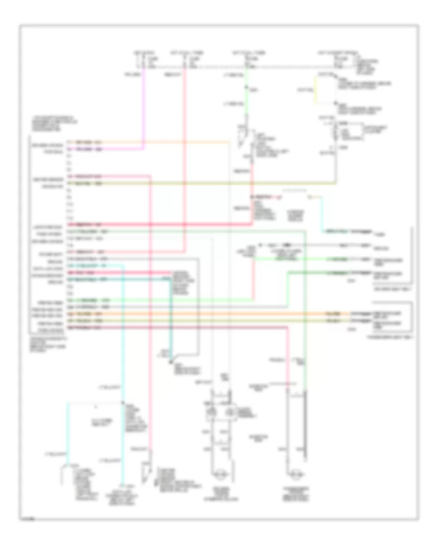
List of elements for Supplemental Restraint Wiring Diagram for Ford Cutaway E350 1998:
- (lower i/p harn, near left kick panel)
- * pin shorting bar is engaged when module connector is disconnected
- 4 wheel anti-lock brake system (4wabs) module (left front frame rail)
- Air bag bracket
- Air bag bracket c210 (right side of dash, behind air bag)
- Air bag diagnostic monitor (behind right side of dash)
- Air bag ind
- Air bag indicator
- C144
- C226
- C241
- C341
- C342
- Center air bag sensor (front center of engine compartment, behind grille)
- Center sensor
- Clock- spring assembly
- Data link conn
- Data link connector (dlc) (below left side of dash)
- Driver's air bag (top of steering column)
- Driver's seat belt
- Drivers air bag
- Fuse 10a
- Fuse 15a
- Fuse 5a
- G200 (left kick panel)
- G201 (behind right side of dash)
- Ground
- Hot at all times
- Hot in run
- Hot in start or run
- I/p fuse panel (behind left side of dash)
- Instrument cluster
- Lamp/warn buz
- Left courtesy lamp switch (mounted in left door jamb)
- Nca
- Pass air bag
- Passenger's air bag (behind right side of dash)
- Passenger's seat belt
- Pnk
- Power (bat)
- Preten feed
- Preten return
- Pretensioner feed
- Pretensioner nca
- Pretensioner return
- Pwr (run)
- Red/pnk
- Return
- S201 (main harness, near right kick panel)
- S221
- S228 (lower dash harn, in data link connector breakout)
- S233
- S265 (lower i/p harness, behind right side of dash)
- S267 (main harness, behind right side of dash)
- Shorting bar
- Timer
- W/ 4 wheel abs only
- Warning buzzer module
 English