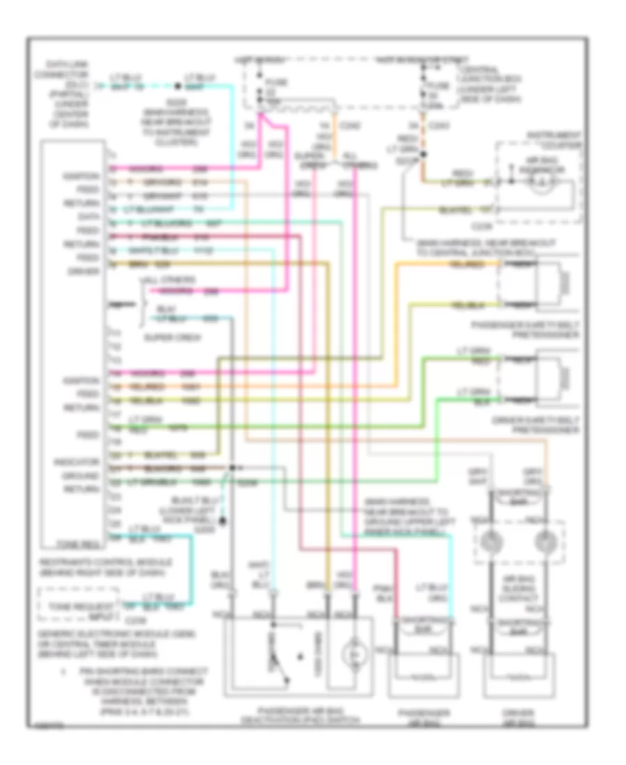
SUPPLEMENTAL RESTRAINTS
Supplemental Restraint Wiring Diagram for Ford Pickup F350 Super Duty 2001
List of elements for Supplemental Restraint Wiring Diagram for Ford Pickup F350 Super Duty 2001:
- (lower left kick panel) g200
- (main harness, near breakout to central junction box)
- (main harness, near breakout to ground upper left inner kick panel)
- (partial) (under center of dash)
- 1000 ohms
- 500 ohms
- Air bag indicator
- Air bag sliding contact
- All others
- C236
- C239
- C242
- C243
- Central junction box (under left side of dash)
- Data
- Data link connector (dlc)
- Driver
- Driver air bag
- Driver safety belt pretensioner
- Feed
- Fuse 10a
- Fuse 30a
- Generic electronic module (gem) or central timer module (behind left side of dash)
- Ground
- Hot in run
- Hot in run or start
- Ignition
- Indicator
- Instrument cluster
- Nca
- Passenger air bag
- Passenger air bag deactivation (pad) switch
- Passenger safety belt pretensioner
- Pin shorting bars connect when module connector is disconnected from harness, between (pins 3-4, 6-7 & 20-21)
- Restraints control module (behind right side of dash)
- Return
- S208
- S229 (main harness, near breakout to instrument cluster)
- S237
- Shorting bar
- Super crew
- Tone req
- Tone request input
 English