TRANSMISSION
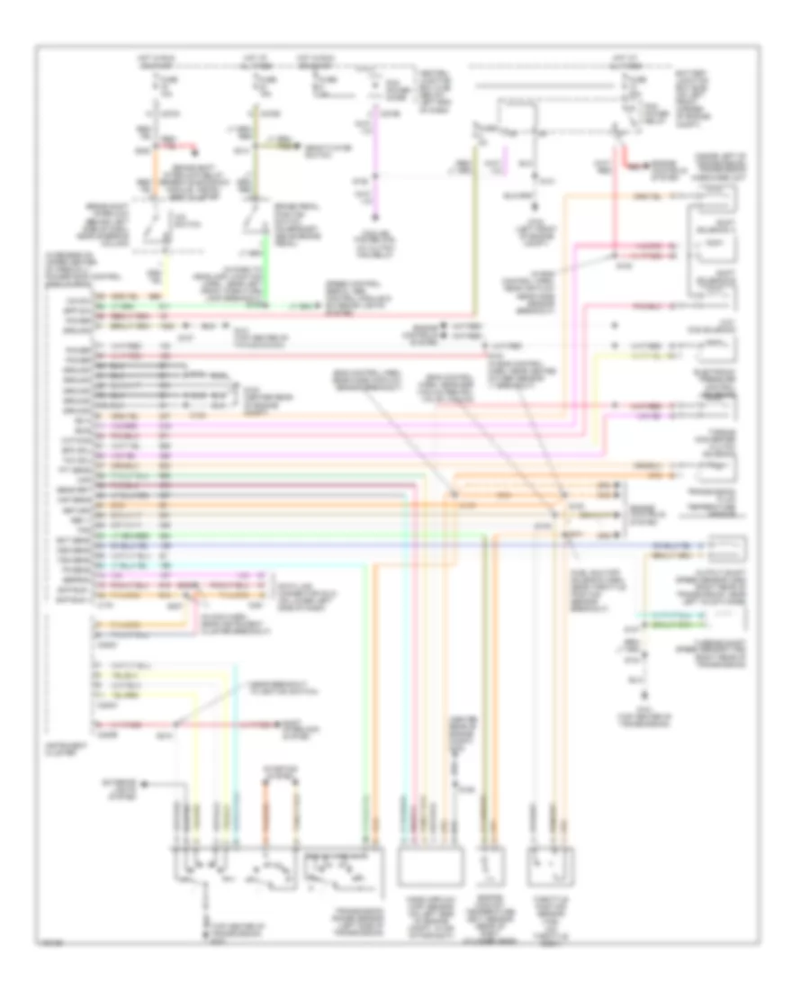
4WD Wiring Diagram for Ford Escape 2004

List of elements for 4WD Wiring Diagram for Ford Escape 2004:
- (in tail lamps harn, near breakout to c421) s415
- C212
- C220b
- C270c
- C270e
- Central junction box (cjb) (below left end of dash)
- Differential lock solenoid (under center rear of vehicle)
- Four- wheel drive
- Four- wheel drive switch
- Four-wheel drive relay (left side of cargo compartment, behind trim)
- Fuse 10a
- Fuse 30a
- G201 (behind center of dash)
- G402 (left rear end of vehicle)
- G403 (left rear end of vehicle)
- Hot at all times
- Hot in run or start
- Instrument cluster
- Interior lights system
- Not used
- Power seat switch, generic electronic module
- S215
- S233
- S309
- S414
A/T Wiring Diagram for Ford Escape 2004
List of elements for A/T Wiring Diagram for Ford Escape 2004:
- (center rear of engine compt) g100
- (eng control harn, near egr vacuum reg sol valve vacuum)
- (eng control harn, near mass air flow sensor breakout)
- (fuel shutoff solenoid harn, near throttle position sensor breakout)
- (in dash to headlamp junction harn, near left front park/turn lamp breakout) s139
- (in eng control harn, near air flow near mass sensor breakout)
- (in main harn, near instrument cluster breakout)
- (in recess on upper center of firewall) powertrain control module (pcm)
- (inside left of transmission) transmission hardware unit
- (near breakout to ignition switch)
- (top center of transmission) g101
- 3-2t/ ccs solenoid
- 3-2t/ccs
- Battery junction box (bjb) (on left front corner of engine compt)
- Bpp sw
- Brake pedal position switch (on bracket, above brake pedal)
- Brake shift interlock (behind left side of dash, near steering column)
- Brake shift interlock relay, generic electronic module, instru- ment cluster
- C175
- C220a
- C220b
- C220c
- C251
- C270b
- C270c
- C270e
- Central junction box (cjb) (below left end of dash)
- Cooling fan relays, a/c clutch fan relay
- Data link connector (dlc) (on lower left side of dash)
- Deactivator switch
- Ect sens
- Eeprom
- Electronic pressure control solenoid
- Engine controls system
- Engine coolant temperature (ect) sensor (rear of right cylinder head)
- Epc sol
- Exterior lights system
- Fuse 10a
- Fuse 15a
- Fuse 30a
- Fuse 3a
- Fuse 5a
- G100 (center rear of engine compt)
- G101 (top center of transmission)
- G104 (left front of engine compt)
- Ground
- Hot at all times
- Hot in run or start
- Instrument cluster
- Maf
- Maf sens
- Mass airflow (maf) sensor (on left side of engine compt, in air intake duct)
- O/d sw
- O/d switch
- Oss sens
- Output shaft speed sensor (oss) (right rear of transmission, near left axle flange)
- Pcm power diode
- Pcm power relay
- Power
- Red
- Ref v
- Return
- S100
- S102
- S103 (in eng control harn, near heated oxygen sensor 11 breakout)
- S104
- S105
- S106
- S107
- S108
- S109
- S128
- S131
- S154
- S206
- S207
- S218
- S222
- S314
- Scp bus +
- Scp bus -
- Sens ret
- Shift interlock system
- Shift solenoid a
- Shift solenoid b
- Speed control servo, abs control module & exterior lights system
- Ss a
- Ss b
- Starting system
- Tan/red
- Tcc sol
- Tft sens
- Throttle position sensor (tps) (on throttle body)
- Torque converter clutch solenoid
- Tps
- Tr sens
- Transmission fluid temperature sensor
- Transmission range sensor (left side of transmission)
- Tss sens
- Turbine shaft speed sensor (tss) (right rear of transmission)
 English