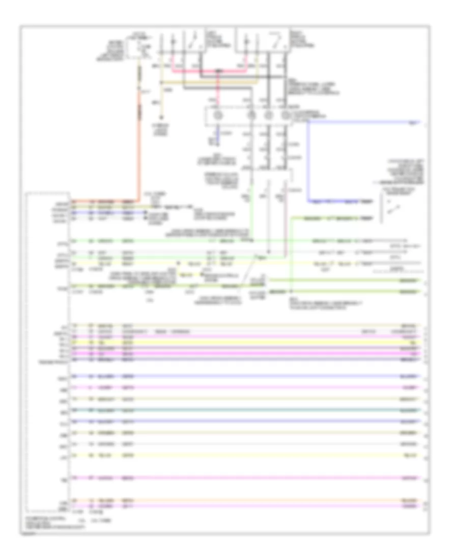
TRANSMISSION
2.0L TURBO
2.0L Turbo, A/T Wiring Diagram for Ford Explorer XLT 2013

List of elements for 2.0L Turbo, A/T Wiring Diagram for Ford Explorer XLT 2013:
- (battery cable wiring assembly, near breakout to 6f35 transmission)
- (not used)
- (under left front of center console)
- 6f35 transmission
- Battery junction box (bjb) (left side of engine compt)
- Body control module (left end of dash)
- Brake shift interlock (w/o console: left side of dash) (w/console: under center console)
- C1381b
- C139
- C1520a
- C1520b
- C212
- C2280b
- C237
- Case gnd
- Cbb90
- Center stack switch assembly
- Cet05
- Cet06
- Cet07
- Cet08
- Cet09
- Cet10
- Cet18
- Cet25
- Cet34
- Cet40
- Computer data lines system
- Fuse 10a
- Fuse 15a
- Fuse 7.5a
- G103 (left front corner of engine compt)
- G200
- Gd120
- Grade assist (w/o trailer tow)
- Hot at all times
- Hot in start or run
- Hs can +
- Hs can -
- I can+
- I can-
- Instrument panel cluster (ipc)
- Interior lights system
- Le111
- Lpc
- Nca
- Oss
- Oss tr gnd
- Oss/tr vpwr
- Powertrain control module (pcm) (center rear of engine compt)
- Pwr gnd
- R/s
- Re406
- Ret24
- S104
- S105
- S106
- S107
- S132
- S202
- S210 (main wiring harness,near breakout to joint connector 6 (hs-can))
- Sbb56
- Sig rtn
- Ssa
- Ssb
- Ssc
- Ssd
- Sse
- Start/run
- Stt-d
- Stt-u
- Tcc
- Tft
- Tft sig rtn
- Tftin
- Tftout/ sigrtn
- Tow haul (w/ trailer tow)
- Tows
- Tr-p
- Transmission control module (tcm) (left side of engine compt)
- Trgnd
- Trs
- Trsw-pin
- Trsw-pn
- Tspc
- Tss
- Tss gnd
- Tss vpwr
- Tss/oss
- Vbatt
- Vdb04
- Vdb05
- Vet26
- Vet27
- Vet32
- Vet33
3.5L
3.5L, A/T Wiring Diagram (1 of 2) for Ford Explorer XLT 2013
List of elements for 3.5L, A/T Wiring Diagram (1 of 2) for Ford Explorer XLT 2013:
- (3.5l turbo) s116 (3.5l) s114
- (main wiring assembly, near breakout to c2123)
- (main wiring assembly, near breakout to defrost/panel/floor mode door actuator) s245
- (or re405)
- (w/o console: left side of dash) (w/console: under center console) (floor shifter) brake shift interlock
- (w/o trailer tow) grade assist
- 3.5l
- 3.5l turbo
- Battery junction box (bjb) (left side of engine compt)
- C140
- C1551b
- C1551e
- C175b
- C175t
- C212
- C218a
- C218b
- C218c
- C237
- C2414a
- C2414d
- Cet05
- Cet06
- Cet07
- Cet08
- Cet09
- Cet10
- Cet19
- Cet25
- Cet34
- Cet42
- Cet43
- Clockspring (top of steering column)
- Computer data lines system
- Engine controls system
- Fuse 7.5a
- G106 (right side of engine compt bulkhead)
- G201 (under right front of center console)
- Gd113
- Hot at all times
- Hs can +
- Hs can -
- Interior lights system
- Kapwr
- Le111
- Left paddle shifter (if equipped)
- Lpc
- Nca
- Oss
- Pnk
- Powertrain control module (pcm) (center rear of engine compt)
- Pwrgnd
- Re406
- Re407
- Res09
- Ret04
- Ret24
- Ret33
- Right paddle shifter (if equipped)
- S117
- S210 (main wiring assembly, near breakout to hs-can joint connector 6)
- S244
- S293
- S294 (steering wheel jumper wiring assembly, near breakout to clockspring)
- S296
- Sbb86
- Sigrtn
- Ssa
- Ssb
- Ssc
- Ssd
- Sse
- Steering column control module (top of steering column)
- Stt-d
- Stt-u
- Tcc
- Tft
- Tows
- Tr-1
- Tr-2
- Tr-3
- Tr-4
- Tspc
- Tss
- Tss/oss/tr gnd
- Vdb04
- Vdb05
- Vet27
- Vet29
- Vet30
- Vet31
- Vet32
- Vref
- W/ column shifter
3.5L, A/T Wiring Diagram (2 of 2) for Ford Explorer XLT 2013
List of elements for 3.5L, A/T Wiring Diagram (2 of 2) for Ford Explorer XLT 2013:
- (or re405)
- 6f50/6f55 transmission
- Auto park
- Body control module (bcm) (left end of dash)
- C2280b
- C263
- Center stack switch assembly (floor shifter)
- Cet05
- Cet06
- Cet07
- Cet08
- Cet09
- Cet10
- Cet19
- Cet25
- Engine controls system
- Fuse 5a
- Fuse 7.5a
- G200 (under left front of center console)
- Hot in start or run
- Interior lights system
- Le111
- Lift gate
- Low gear selector switch (column shifter)
- Lpc
- Navigation system
- Oss
- Re406
- Ret04
- Ret24
- Ret33
- S1006
- S1007 (3.5l turbo) (engine control sensor & fuel charge wiring assembly, near breakout to camshaft position 11 (cmp11) sensor)
- S159 (front wheel drive (fwd) engine wiring assembly, in breakout to 6f50/6f55 transmission)
- S202
- S217
- Ssa
- Ssb
- Ssc
- Ssd
- Sse
- Tcc
- Tft
- Tft sigrtn
- Towhaul (w/ triler tow)
- Tr gnd
- Tr-1
- Tr-2
- Tr-3
- Tr-4
- Trs
- Trunk, tailgate, fuel doors system
- Tspc
- Tss
- Tss/oss gnd
- Tss/oss vpwr
- Vet27
- Vet29
- Vet30
- Vet31
- Vet32
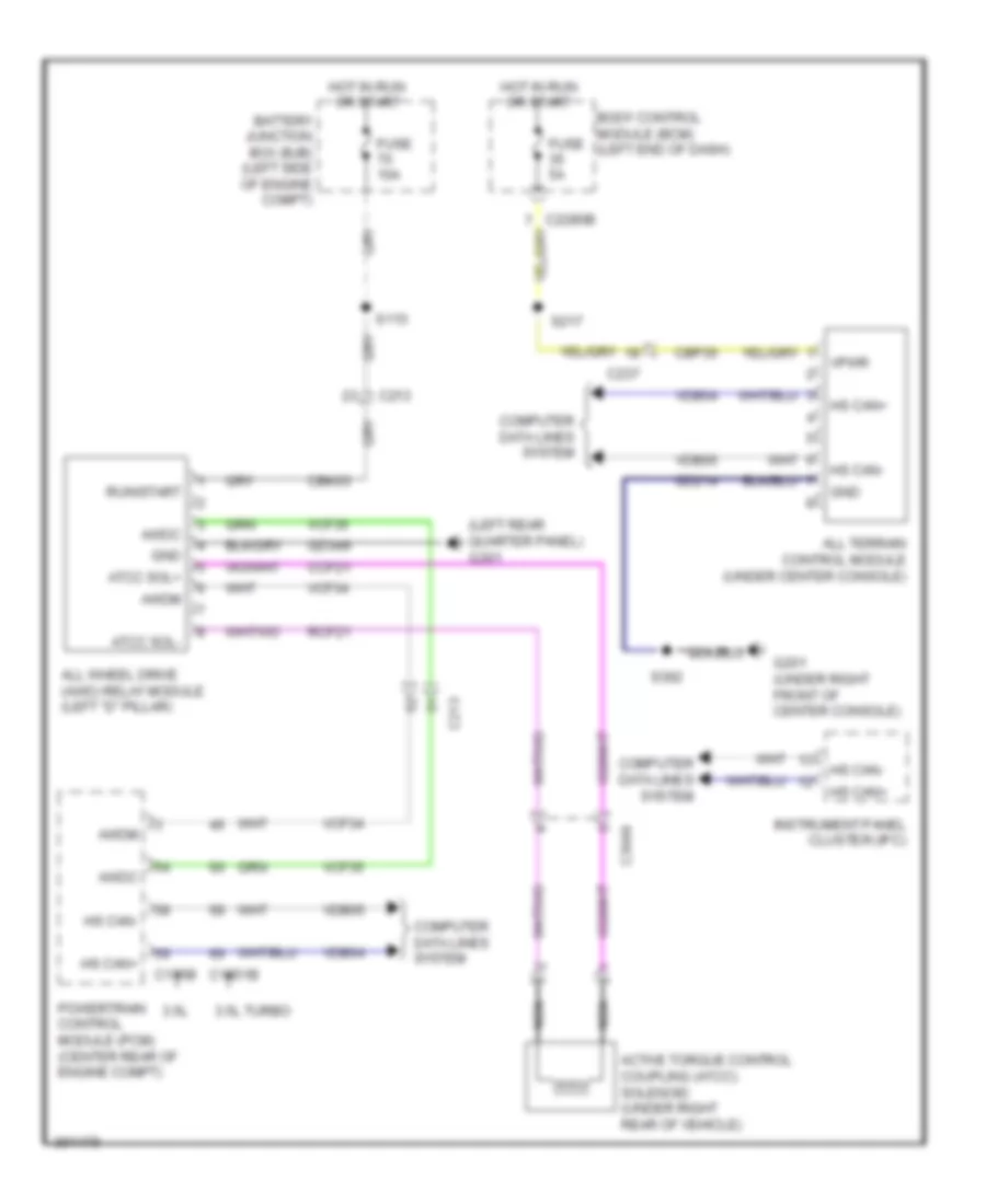
3.5L, AWD Wiring Diagram for Ford Explorer XLT 2013
List of elements for 3.5L, AWD Wiring Diagram for Ford Explorer XLT 2013:
- (left rear quarter panel) g301
- 3.5l
- 3.5l turbo
- Active torque control coupling (atcc) solenoid (under right rear of vehicle)
- All terrain control module (under center console)
- All wheel drive (awd) relay module (left "d" pillar)
- Atcc sol+
- Atcc sol-
- Awdc
- Awdm
- Battery junction box (bjb) (left side of engine compt)
- Body control module (bcm) (left end of dash)
- C1551b
- C175b
- C213
- C237
- C3049
- Cbk03
- Cbp35
- Ccf21
- Computer data lines system
- Fuse 10a
- Fuse 5a
- G201 (under right front of center console)
- Gd214
- Gd349
- Gnd
- Hot in run or start
- Hs can+
- Hs can-
- Instrument panel cluster (ipc)
- Nca
- Powertrain control module (pcm) (center rear of engine compt)
- Rcf21
- Run/start
- S113
- S217
- S392
- Vcf34
- Vcf35
- Vdb04
- Vdb05
- Vpwr
3.5L TWIN TURBO
3.5L Twin Turbo, A/T Wiring Diagram (1 of 2) for Ford Explorer XLT 2013
List of elements for 3.5L Twin Turbo, A/T Wiring Diagram (1 of 2) for Ford Explorer XLT 2013:
- (3.5l turbo) s116 (3.5l) s114
- (main wiring assembly, near breakout to c2123)
- (main wiring assembly, near breakout to defrost/panel/floor mode door actuator) s245
- (or re405)
- (w/o console: left side of dash) (w/console: under center console) (floor shifter) brake shift interlock
- (w/o trailer tow) grade assist
- 3.5l
- 3.5l turbo
- Battery junction box (bjb) (left side of engine compt)
- C140
- C1551b
- C1551e
- C175b
- C175t
- C212
- C218a
- C218b
- C218c
- C237
- C2414a
- C2414d
- Cet05
- Cet06
- Cet07
- Cet08
- Cet09
- Cet10
- Cet19
- Cet25
- Cet34
- Cet42
- Cet43
- Clockspring (top of steering column)
- Computer data lines system
- Engine controls system
- Fuse 7.5a
- G106 (right side of engine compt bulkhead)
- G201 (under right front of center console)
- Gd113
- Hot at all times
- Hs can +
- Hs can -
- Interior lights system
- Kapwr
- Le111
- Left paddle shifter (if equipped)
- Lpc
- Nca
- Oss
- Pnk
- Powertrain control module (pcm) (center rear of engine compt)
- Pwrgnd
- Re406
- Re407
- Res09
- Ret04
- Ret24
- Ret33
- Right paddle shifter (if equipped)
- S117
- S210 (main wiring assembly, near breakout to hs-can joint connector 6)
- S244
- S293
- S294 (steering wheel jumper wiring assembly, near breakout to clockspring)
- S296
- Sbb86
- Sigrtn
- Ssa
- Ssb
- Ssc
- Ssd
- Sse
- Steering column control module (top of steering column)
- Stt-d
- Stt-u
- Tcc
- Tft
- Tows
- Tr-1
- Tr-2
- Tr-3
- Tr-4
- Tspc
- Tss
- Tss/oss/tr gnd
- Vdb04
- Vdb05
- Vet27
- Vet29
- Vet30
- Vet31
- Vet32
- Vref
- W/ column shifter
3.5L Twin Turbo, A/T Wiring Diagram (2 of 2) for Ford Explorer XLT 2013
List of elements for 3.5L Twin Turbo, A/T Wiring Diagram (2 of 2) for Ford Explorer XLT 2013:
- (or re405)
- 6f50/6f55 transmission
- Auto park
- Body control module (bcm) (left end of dash)
- C2280b
- C263
- Center stack switch assembly (floor shifter)
- Cet05
- Cet06
- Cet07
- Cet08
- Cet09
- Cet10
- Cet19
- Cet25
- Engine controls system
- Fuse 5a
- Fuse 7.5a
- G200 (under left front of center console)
- Hot in start or run
- Interior lights system
- Le111
- Lift gate
- Low gear selector switch (column shifter)
- Lpc
- Navigation system
- Oss
- Re406
- Ret04
- Ret24
- Ret33
- S1006
- S1007 (3.5l turbo) (engine control sensor & fuel charge wiring assembly, near breakout to camshaft position 11 (cmp11) sensor)
- S159 (front wheel drive (fwd) engine wiring assembly, in breakout to 6f50/6f55 transmission)
- S202
- S217
- Ssa
- Ssb
- Ssc
- Ssd
- Sse
- Tcc
- Tft
- Tft sigrtn
- Towhaul (w/ triler tow)
- Tr gnd
- Tr-1
- Tr-2
- Tr-3
- Tr-4
- Trs
- Trunk, tailgate, fuel doors system
- Tspc
- Tss
- Tss/oss gnd
- Tss/oss vpwr
- Vet27
- Vet29
- Vet30
- Vet31
- Vet32
3.5L Twin Turbo, AWD Wiring Diagram for Ford Explorer XLT 2013
List of elements for 3.5L Twin Turbo, AWD Wiring Diagram for Ford Explorer XLT 2013:
- (left rear quarter panel) g301
- 3.5l
- 3.5l turbo
- Active torque control coupling (atcc) solenoid (under right rear of vehicle)
- All terrain control module (under center console)
- All wheel drive (awd) relay module (left "d" pillar)
- Atcc sol+
- Atcc sol-
- Awdc
- Awdm
- Battery junction box (bjb) (left side of engine compt)
- Body control module (bcm) (left end of dash)
- C1551b
- C175b
- C213
- C237
- C3049
- Cbk03
- Cbp35
- Ccf21
- Computer data lines system
- Fuse 10a
- Fuse 5a
- G201 (under right front of center console)
- Gd214
- Gd349
- Gnd
- Hot in run or start
- Hs can+
- Hs can-
- Instrument panel cluster (ipc)
- Nca
- Powertrain control module (pcm) (center rear of engine compt)
- Rcf21
- Run/start
- S113
- S217
- S392
- Vcf34
- Vcf35
- Vdb04
- Vdb05
- Vpwr