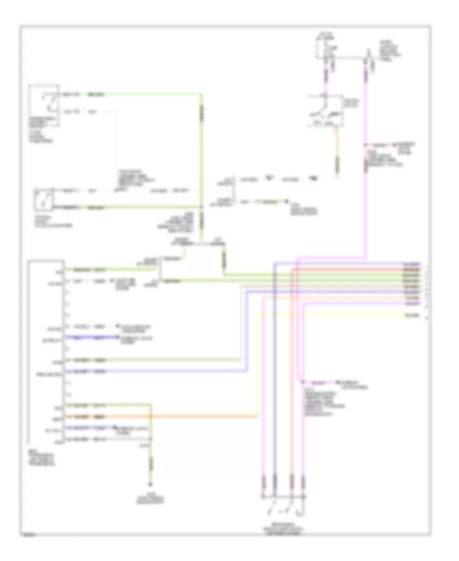
TRANSMISSION
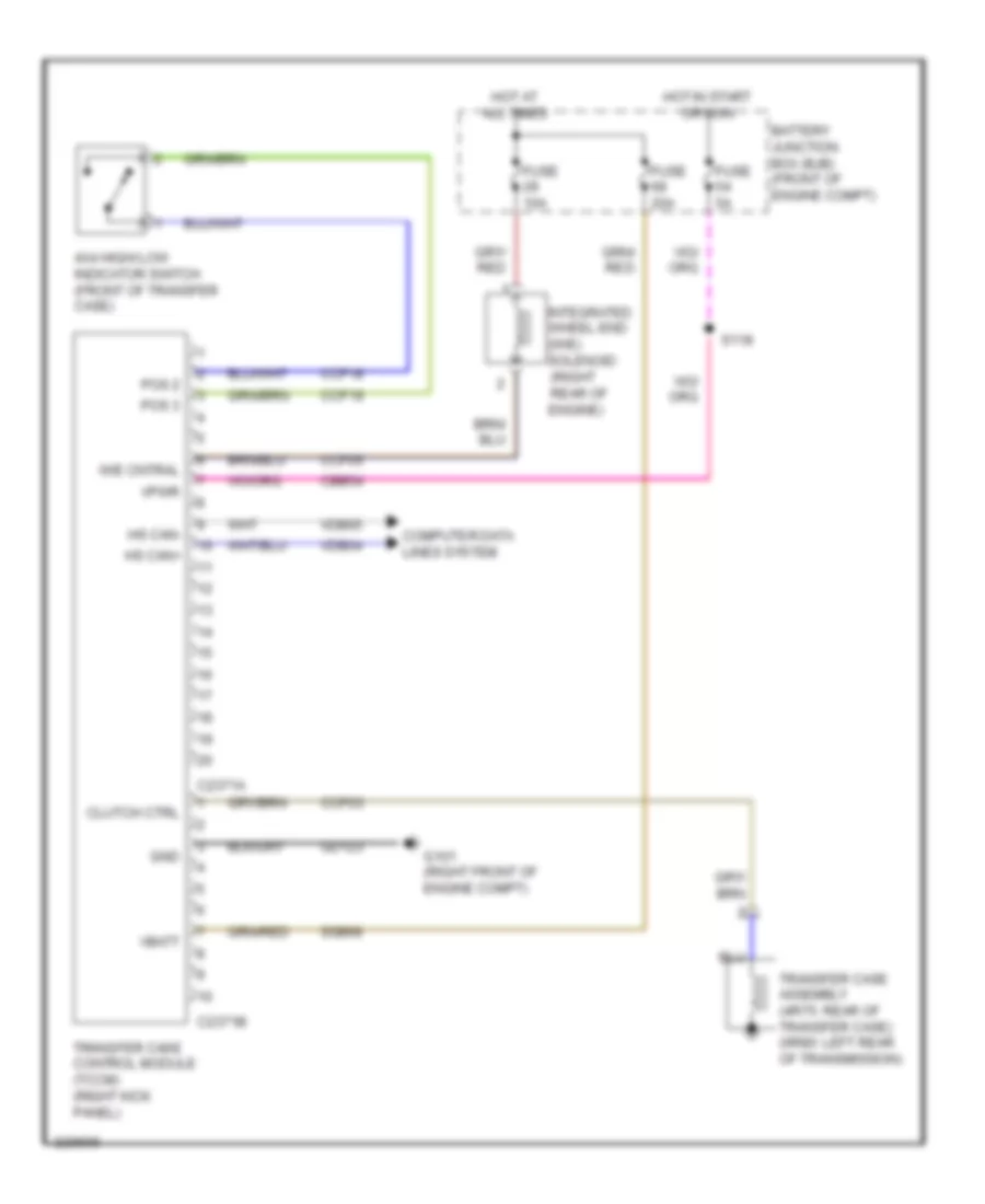
4WD Wiring Diagram, Electronic for Ford Pickup F150 2010

List of elements for 4WD Wiring Diagram, Electronic for Ford Pickup F150 2010:
- (w/ electronically locking hubs)
- (w/ svt raptor)
- 2 hi
- 4 hi
- 4 lo
- Battery junction box (bjb) (front of engine compt)
- C2280b
- C2371a
- C2371b
- Cbb54
- Ccf01
- Ccf03
- Ccf05
- Ccf07
- Ccf08
- Ccf11
- Ccf13
- Ccf14
- Ccf15
- Ccf16
- Ccf17
- Ccf31
- Ccf32
- Ccf33
- Clutch coil
- Clutch solenoid
- Computer data lines system
- Diff lock ctrl
- Easy led
- Electronic locking differential (eld) field coil (under left rear of vehicle)
- Elock led
- Fuse 10a
- Fuse 20a
- Fuse 5a
- G101 (right front of engine compt)
- G202 (left side of dash)
- G203 (left side of dash)
- Gd123
- Gnd 1
- Gnd 2
- Hi to low
- Hot at all times
- Hot in start or run
- Hs can+
- Hs can-
- Integrated wheel end (iwe) solenoid (left side of engine compt)
- Interior lights system
- Iwe cntral
- Locker mode sw
- Low to hi
- Mode select switch (mss)
- Mtr-ccw
- Mtr-cw
- Off road switch
- Off-road mode switch
- Pos 1
- Pos 1 mtr
- Pos 2
- Pos 2 mtr
- Pos 3
- Pos 3 mtr
- Pos 4
- Pos 4 mtr
- Pos rtn
- Rcf09
- Rcf13
- S118
- S223
- S329
- S331
- Smart junction box (sjb) (right kick panel)
- Ssb20
- Ssb68
- Sw cntral
- Swrtn
- Transfer case assembly (4r75: rear of transfer case) (6r80: left rear of transmission)
- Transfer case control module (tccm) (right kick panel)
- Vbatt
- Vdb04
- Vdb05
- Vpwr
- W/ electronically locking hubs
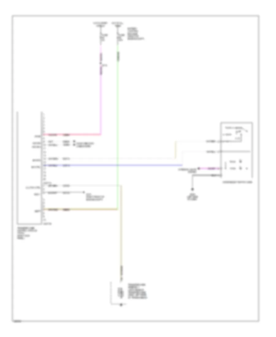
4WD Wiring Diagram, Mechanical for Ford Pickup F150 2010
List of elements for 4WD Wiring Diagram, Mechanical for Ford Pickup F150 2010:
- 4x4 high/ low indicator switch (front of transfer case)
- Battery junction box (bjb) (front of engine compt)
- C2371a
- C2371b
- Cbb54
- Ccf03
- Ccf05
- Ccf18
- Ccf19
- Clutch ctrl
- Computer data lines system
- Fuse 10a
- Fuse 20a
- Fuse 5a
- G101 (right front of engine compt)
- Gd123
- Gnd
- Hot at all times
- Hot in start or run
- Hs can+
- Hs can-
- Integrated wheel end (iwe) solenoid (right rear of engine)
- Iwe cntral
- Pos 2
- Pos 3
- S118
- Ssb68
- Transfer case assembly (4r75: rear of transfer case) (6r80: left rear of transmission)
- Transfer case control module (tccm) (right kick panel)
- Vbatt
- Vdb04
- Vdb05
- Vpwr
4WD Wiring Diagram, Torque on Demand for Ford Pickup F150 2010
List of elements for 4WD Wiring Diagram, Torque on Demand for Ford Pickup F150 2010:
- 2 hi
- 4 hi
- 4 lo
- Battery junction box (bjb) (front of engine compt)
- C2371a
- C2371b
- Cbb54
- Ccf03
- Ccf13
- Clutch ctrl
- Clutch solenoid
- Computer data lines system
- Fuse 20a
- Fuse 5a
- G101 (right front of engine compt)
- G202 (left side of dash)
- Gd123
- Gnd 1
- Hot at all times
- Hot in start or run
- Hs can+
- Hs can-
- Interior lights system
- Mode select switch (mss)
- Rcf13
- S118
- Sbb68
- Sw ctrl
- Sw rtn
- Transfer case assembly (4r75: rear of transfer case) (6r80: left rear of transmission)
- Transfer case control module (tccm) (right kick panel)
- Vbatt
- Vdb04
- Vdb05
- Vpwr
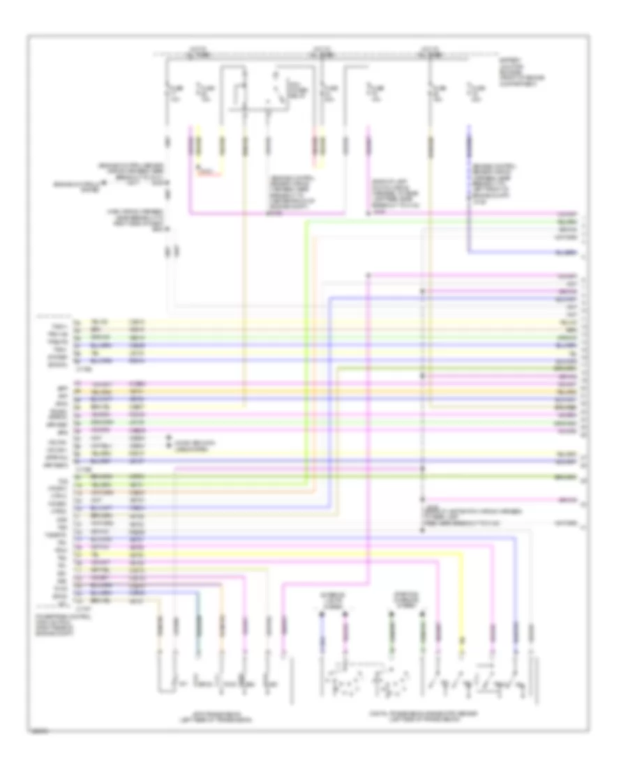
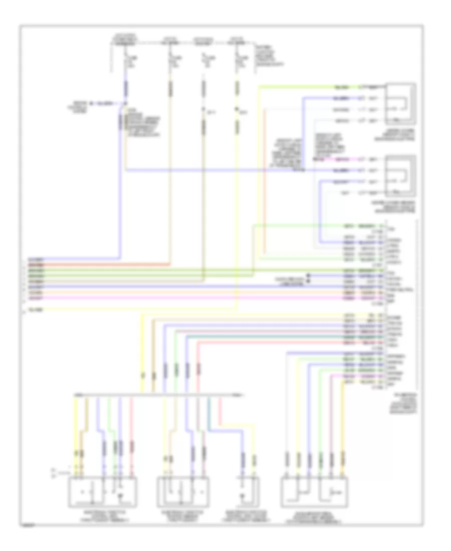
A/T Wiring Diagram, 4 Speed (1 of 2) for Ford Pickup F150 2010
List of elements for A/T Wiring Diagram, 4 Speed (1 of 2) for Ford Pickup F150 2010:
- (backup lamp switch wiring harness, to rear lamp feed near breakout to c140)
- (engine control sensor wiring harness, near breakout to center front of engine compt) s125
- (engine control sensor wiring harness, near breakout to g101) s105
- (engine control sensor wiring harness, near breakout to left front of engine compt)
- (main wiring harness, near breakout to right side of dash) s222
- 4r75 transmission (left rear of transmission)
- App
- App2
- Apprtn2
- Appvref
- Appvref2
- Battery junction box (bjb) (front of engine compartment)
- Bpp
- Bps
- C175b
- C175e
- C175t
- Ccb08
- Ce233
- Ce234
- Ce412
- Ce418
- Ce426
- Ce607
- Ces09
- Cet05
- Cet18
- Cet19
- Cet34
- Computer data lines system
- Digital transmission range (dtr) sensor (left side of transmission)
- Engine controls system
- Epcs
- Etcref
- Etcrtn
- Exterior lights system
- Fuse 10a
- Fuse 15a
- Fuse 20a
- Fuse 40a
- Ho2s12
- Ho2s22
- Hot at all times
- Hs can+
- Hs can-
- Htr12
- Htr22
- Le134
- Le136
- Le137
- Oss
- Pcm power relay
- Pcmrc apprtn
- Powertrain control module (pcm) (right rear of engine compt)
- Re134
- Re136
- Re137
- Re406
- S101
- S129
- S146 (backup lamp switch wiring harness, to rear lamp feed near breakout to c140)
- S147
- Ss1
- Ss2
- Starting/ charging system
- T-sigrtn
- Tacm+
- Tacm-
- Tccs
- Tcs
- Tft
- Tps1-ns
- Tps2-ps
- Tr1
- Tr2
- Tr3a
- Tr4
- Tss
- Vdb04
- Vdb05
- Ve701
- Ve702
- Ve731
- Ve733
- Ve818
- Ve819
- Vet26
- Vet27
- Vet28
- Vet29
- Vet30
- Vet31
- Vet33
A/T Wiring Diagram, 4 Speed (2 of 2) for Ford Pickup F150 2010
List of elements for A/T Wiring Diagram, 4 Speed (2 of 2) for Ford Pickup F150 2010:
- (main wiring harness, near breakout to right side of dash) s226
- Accelerator pedal position (app) sensor (top of brake pedalassembly)
- Bpp
- Brake pedal position (bpp) switch (left side of dash)
- Electronic throttle control (etc) (throttle body assembly)
- Exterior lights system
- Floor shifter (w/ floor shifter)
- Heated oxygen sensor (ho2s) 12 (engine exhaust pipe)
- Heated oxygen sensor sensor (ho2s) 22 (engine exhaust pipe)
- Nca
- Output shaft speed (oss) sensor (left side of transmission)
- Overdrive cancel switch (w/ column shifter) (steering column)
- S112 (engine control sensor wiring harness, near breakout front center of engine comp)
- S232 (main wiring harness, near breakout to c238)
- Smart junction box (sjb) (right kick panel) c2280b
- Transmission control switch
- Turbine shaft speed (tss) sensor (left side of transmission)
A/T Wiring Diagram, 6 Speed (1 of 2) for Ford Pickup F150 2010
List of elements for A/T Wiring Diagram, 6 Speed (1 of 2) for Ford Pickup F150 2010:
- (main wiring harness, near breakout to right side of dash) s222
- 6r80 transmission (left rear of transmission)
- Acc
- Bpp
- Brake pedal position (bpp) switch (left side of dash)
- Bu relay +
- C2280a
- C2280b
- Cbb53
- Cet34
- Cet39
- Cet47
- Cls28
- Computer data lines system
- Except svt raptor
- Exterior lights system
- Floor shifter (if equipped)
- Fuse 15a
- G100 (right side of engine compt)
- Gd113
- Gnd
- Hot at all times
- Hs can+
- Hs can-
- Ignition switch
- Nca
- Off
- Park neutral
- Rly coil-
- Run
- S112 (engine control sensor wiring harness, near breakout to center front of engine compt)
- S113
- S149
- S226 (main wiring harness, near breakout to right side of dash)
- S230
- S232 (main wiring harness, near breakout to c238)
- Sbb46
- Smart junction box (sjb) (right kick panel)
- Start
- Svt raptor
- Tcs
- Towhaul switch (w/ column shifter)
- Transmission control switch
- Vbatt
- Vdb04
- Vdb05
- Vpwr
A/T Wiring Diagram, 6 Speed (2 of 2) for Ford Pickup F150 2010
List of elements for A/T Wiring Diagram, 6 Speed (2 of 2) for Ford Pickup F150 2010:
- (backup lamp switch wiring harness, to rear lamp feed near breakout to c140) s146
- (backup lamp switch wiring harness, to rear lamp feed near breakout to left center of transmission) s148
- 4.6l
- 5.4l
- Accelerator pedal position (app) sensor (top of brake pedalassembly)
- App
- App2
- Apprtn
- Apprtn2
- Appvref
- Appvref2
- Battery junction box (bjb) (front of engine compt)
- Bpp
- Bps
- C175b
- C175e
- C175t
- Ccb08
- Ce233
- Ce234
- Ce412
- Ce426
- Ces09
- Cet34
- Cet39
- Computer data lines system
- Electronic throttle control (etc) (throttle body assembly)
- Electronic throttle control (etc) motor (throttle body assembly)
- Electronic throttle position sensor (throttle body)
- Engine controls system
- Etcref
- Etcrtn
- Fuse 10a
- Fuse 15a
- Fuse 20a
- Fuse 5a
- Heated oxygen sensor (ho2s) 12 (engine exhaust pipe)
- Heated oxygen sensor sensor (ho2s) 22 (engine exhaust pipe)
- Ho2s12
- Ho2s22
- Hot at all times
- Hot in run or start
- Hot w/ pcm power relay energized
- Hs can+
- Hs can-
- Htr12
- Htr22
- Le134
- Le136
- Le137
- Park neutral
- Powertrain control module (pcm) (right rear of engine compt)
- Re134
- Re136
- Re137
- Re406
- S101
- S117
- S129 (engine control sensor wiring harness, near breakout to left front of engine compt)
- Sigrtn
- Tacm+
- Tacn-
- Tcs
- Tps1-ns
- Tps2-ps
- Vdb04
- Vdb05
- Ve701
- Ve702
- Ve731
- Ve733
- Ve818
- Ve819