TRANSMISSION
2.3L
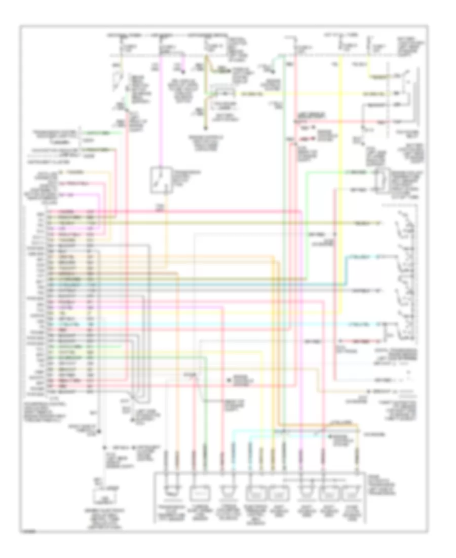
2.3L, A/T Wiring Diagram for Ford Ranger 2001

List of elements for 2.3L, A/T Wiring Diagram for Ford Ranger 2001:
- (behind left side of dash) s227
- (dlc) (partial) (fastened to bottom of dash, near steering column)
- (left front of engine compt)
- (left rear of engine compt) s113
- (left side of transmission) digital transmission range sensor
- (on engine)
- (on engine) s149
- (top rear of engine compt)
- 5r44e automatic transmission (left side of transmission)
- Anti-lock brakes system
- Battery junction box (left rear of engine compt)
- Bpp
- Brake pedal position switch (behind left side of dash, above brake pedal)
- C175
- C220a
- C220b
- Central junction box (behind left side of dash)
- Cht
- Cylinder head temperature (cht) sensor (right side of cylinder head)
- Data link connector
- Deactivator switch
- Dlc
- Dlc (+)
- Dlc (-)
- Electronic pressure control (epc) solenoid
- Engine controls system
- Epc
- Exterior lights system
- Fuse 10a
- Fuse 20a
- Fuse 25a
- Fuse 30a
- Fuse 7.5a
- G104 (left front of engine compt)
- G205 (under left front seat)
- Ground
- Hot at all times
- Hot in run
- Hot in run or start
- Instrument cluster
- Intermediate shaft speed (iss) sensor (left rear of trans)
- Iss
- Kapwr
- Malfunction indicator lamp (mil)
- Mil
- Nca
- O/d off
- Oss
- Output shaft speed (oss) sensor (left rear of trans)
- Pcm power diode
- Pcm power relay
- Power
- Powertrain control module (pcm) (right rear of engine compartment, through firewall)
- R p
- Red
- S107
- S117
- S118
- S137
- S143
- S150 (on engine)
- S151 (on engine)
- S152 (on engine)
- S153
- S154
- S236
- S238
- Shift solenoids
- Sig rtn
- Ss a
- Ss b
- Ss c
- Ss d
- Tcc
- Tcil
- Tcs
- Tft
- Throttle position (tp) sensor (top left front of engine, on throttle body)
- Torque converter clutch (tcc) solenoid
- Tr1
- Tr2
- Tr3a
- Tr4
- Transmission control indicator lamp (tcil)
- Transmission control switch (tcs)
- Transmission fluid temperature (tft) sensor
- Tss
- Turbine shaft speed (tss) sensor
- Vref
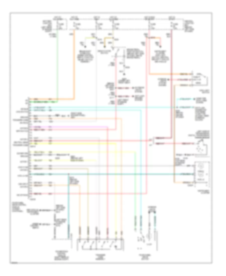
4WD Wiring Diagram for Ford Ranger 2001
List of elements for 4WD Wiring Diagram for Ford Ranger 2001:
- (behind left side of dash) s213
- (behind left side of dash) s227
- (left front of engine compt)
- (left side of transmission) digital transmission range sensor
- (right side rocker panel) g201
- 4wd hi
- 4wd hi ind
- 4wd lo
- 4wd lo ind
- 4wd switch
- A/t
- Anti-lock brakes system
- Battery junction box (left rear of engine compt)
- Bpp switch
- Brake pedal position switch (behind left side of dash, above brake pedal)
- Brake shift interlock, speed control servo, function select switch assembly
- C175
- C220a
- C281a
- C281b
- Central junction box (behind left side of dash)
- Computer data lines system
- Data link connector (fastened to bottom of dash, near steering column)
- Deactivator switch
- Exterior lights system
- Four-wheel drive control module (in right kick panel)
- Four-wheel drive switch
- Fuse 15a
- Fuse 20a
- Fuse 7.5a
- G106 (top rear of engine compt)
- G204 (behind left side of dash)
- G205 (under left front seat)
- Gem module, instrument cluster
- Ground
- Head
- Hot at all times
- Hot in run
- Hot in run or start
- Hot in start
- Ign (run)
- Ign (st/run)
- Illum
- Instrument cluster
- Instrument cluster, main light switch, central security module, gem module
- Interior lights system
- Interior lights system (dimmer)
- Iso bus
- M/t
- Main light switch
- Motor 1
- Motor 2
- Motor 3
- Motor 4
- Motor 5
- Neutral sens
- Off
- Park
- Powertrain control module (right rear of engine compt)
- S117
- S145
- S203
- S208 (behind center of dash)
- S209
- S215 (behind left side of dash)
- S216
- S218
- S236
- S238
- Sig return
- Speed control servo
- Transfer case
- Transfer case assembly
- Vss input
2.5L
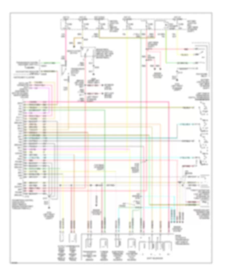
2.5L, A/T Wiring Diagram, 4R44E for Ford Ranger 2001
List of elements for 2.5L, A/T Wiring Diagram, 4R44E for Ford Ranger 2001:
- (left rear of engine compt) s113
- (left side of radiator support) g104
- (on engine)
- (rear top of engine compt)
- (right side of firewall) g106
- 4r44e automatic transmission (left side of transmission)
- Battery junction box
- Battery junction box (left rear of engine compt)
- Bpp
- Brake pedal position switch (on brake pedal support)
- C175
- C201b
- C220a
- C220b
- Ccs
- Central junction box (behind left side of dash)
- Coast clutch solenoid (css)
- Cse gnd
- Data link connector (dlc) (partial) (fastened to bottom of dash, near steering column)
- Digital transmission range sensor (left side of trans)
- Dlc
- Dlc (+)
- Dlc (-)
- Drl module, back-up lamps, pulse vacuum hublock solenoid switch
- Ect
- Electronic pressure control (epc) solenoid
- Engine controls (ignition coil, radio noise capacitor)
- Engine controls system
- Engine coolant temperature (ect) sensor (top right front of eng, in water outlet tube)
- Epc
- Fuse 19 25a
- Fuse 2 10a
- Fuse 21 10a
- Fuse 41 20a
- Fuse 7 30a
- Fuse 9 7.5a
- G104 (left side of upper radiator support)
- Generic electronic module (gem)/ central timer module (ctm) (center of dash)
- Hot at all times
- Hot in run
- Hot in start or run
- Instrument cluster
- Instrument cluster, cruise control
- Kapwr
- Malfunction indicator lamp (mil)
- Mil
- O/d off
- Passive anti-theft system module
- Pcm power diode
- Pcm power relay
- Power
- Powertrain control module (pcm) (right rear of engine compartment, through firewall)
- Pwr gnd
- R p
- Red
- S107
- S116 (left rear side of engine compt)
- S117 (left front of engine compt)
- S118
- S136 (rear top of engine compt)
- S137 (on engine)
- S139 (on engine)
- S141
- S143
- S144 (on trans)
- Shift solenoid (ssa)
- Shift solenoid (ssb)
- Shift solenoid (ssc)
- Sig rtn
- Ss1
- Ss2
- Ss3
- Tcc
- Tcil
- Tcs
- Tft
- Throttle position (tp) sensor (top right side of engine, on throttle body)
- Torque converter clutch (tcc) solenoid
- Tr1
- Tr2
- Tr4
- Transmission control indicator lamp (tcil)
- Transmission control switch (tcs)
- Transmission fluid temperature (tft) sensor
- Tss
- Turbine shaft speed (tss) sensor
- Vref
- Vss
- Vss output
4WD Wiring Diagram for Ford Ranger 2001
List of elements for 4WD Wiring Diagram for Ford Ranger 2001:
- (behind left side of dash) s213
- (behind left side of dash) s227
- (left front of engine compt)
- (left side of transmission) digital transmission range sensor
- (right side rocker panel) g201
- 4wd hi
- 4wd hi ind
- 4wd lo
- 4wd lo ind
- 4wd switch
- A/t
- Anti-lock brakes system
- Battery junction box (left rear of engine compt)
- Bpp switch
- Brake pedal position switch (behind left side of dash, above brake pedal)
- Brake shift interlock, speed control servo, function select switch assembly
- C175
- C220a
- C281a
- C281b
- Central junction box (behind left side of dash)
- Computer data lines system
- Data link connector (fastened to bottom of dash, near steering column)
- Deactivator switch
- Exterior lights system
- Four-wheel drive control module (in right kick panel)
- Four-wheel drive switch
- Fuse 15a
- Fuse 20a
- Fuse 7.5a
- G106 (top rear of engine compt)
- G204 (behind left side of dash)
- G205 (under left front seat)
- Gem module, instrument cluster
- Ground
- Head
- Hot at all times
- Hot in run
- Hot in run or start
- Hot in start
- Ign (run)
- Ign (st/run)
- Illum
- Instrument cluster
- Instrument cluster, main light switch, central security module, gem module
- Interior lights system
- Interior lights system (dimmer)
- Iso bus
- M/t
- Main light switch
- Motor 1
- Motor 2
- Motor 3
- Motor 4
- Motor 5
- Neutral sens
- Off
- Park
- Powertrain control module (right rear of engine compt)
- S117
- S145
- S203
- S208 (behind center of dash)
- S209
- S215 (behind left side of dash)
- S216
- S218
- S236
- S238
- Sig return
- Speed control servo
- Transfer case
- Transfer case assembly
- Vss input
3.0L
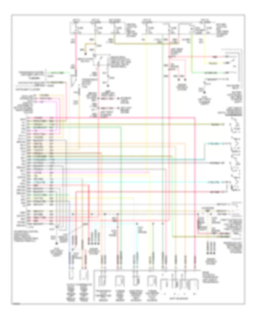
3.0L, A/T Wiring Diagram for Ford Ranger 2001
List of elements for 3.0L, A/T Wiring Diagram for Ford Ranger 2001:
- (behind left side of dash) s227
- (dlc) (partial) (fastened to bottom of dash, near steering column)
- (left front of engine compt)
- (left rear of engine compt) s113
- (left side of transmission) digital transmission range sensor
- (on engine)
- (on engine) s104
- (on engine) s106
- (on trans)
- (top rear of engine compt)
- 5r44e automatic transmission (left side of transmission)
- Anti-lock brakes system
- Battery junction box (left rear of engine compt)
- Bpp
- Brake pedal position switch (behind left side of dash, above brake pedal)
- C175
- C220a
- C220b
- Central junction box (behind left side of dash)
- Data link connector
- Deactivator switch
- Dlc
- Dlc (+)
- Dlc (-)
- Ect
- Electronic pressure control (epc) solenoid
- Engine controls system
- Engine coolant temperature (ect) sensor (top front of engine)
- Epc
- Exterior lights system
- Fuse 10a
- Fuse 20a
- Fuse 25a
- Fuse 30a
- Fuse 7.5a
- G104 (left front of engine compt)
- G205 (under left front seat)
- Ground
- Hot at all times
- Hot in run
- Hot in run or start
- Instrument cluster
- Intermediate shaft speed (iss) sensor (left rear of trans)
- Iss
- Kapwr
- Malfunction indicator lamp (mil)
- Mil
- Nca
- O/d off
- Oss
- Output shaft speed (oss) sensor (left rear of trans)
- Pcm power diode
- Pcm power relay
- Power
- Powertrain control module (pcm) (right rear of engine compartment, through firewall)
- R p
- Red
- S100
- S107
- S117
- S118
- S129 (top rear of engine compt)
- S137
- S139
- S143
- S236
- S238
- Shift solenoids
- Sig rtn
- Ss a
- Ss b
- Ss c
- Ss d
- Tcc
- Tcil
- Tcs
- Tft
- Throttle position (tp) sensor (top left front of engine, on throttle body)
- Torque converter clutch (tcc) solenoid
- Tr1
- Tr2
- Tr3a
- Tr4
- Transmission control indicator lamp (tcil)
- Transmission control switch (tcs)
- Transmission fluid temperature (tft) sensor
- Tss
- Turbine shaft speed (tss) sensor
- Vref
4WD Wiring Diagram for Ford Ranger 2001
List of elements for 4WD Wiring Diagram for Ford Ranger 2001:
- (behind left side of dash) s213
- (behind left side of dash) s227
- (left front of engine compt)
- (left side of transmission) digital transmission range sensor
- (right side rocker panel) g201
- 4wd hi
- 4wd hi ind
- 4wd lo
- 4wd lo ind
- 4wd switch
- A/t
- Anti-lock brakes system
- Battery junction box (left rear of engine compt)
- Bpp switch
- Brake pedal position switch (behind left side of dash, above brake pedal)
- Brake shift interlock, speed control servo, function select switch assembly
- C175
- C220a
- C281a
- C281b
- Central junction box (behind left side of dash)
- Computer data lines system
- Data link connector (fastened to bottom of dash, near steering column)
- Deactivator switch
- Exterior lights system
- Four-wheel drive control module (in right kick panel)
- Four-wheel drive switch
- Fuse 15a
- Fuse 20a
- Fuse 7.5a
- G106 (top rear of engine compt)
- G204 (behind left side of dash)
- G205 (under left front seat)
- Gem module, instrument cluster
- Ground
- Head
- Hot at all times
- Hot in run
- Hot in run or start
- Hot in start
- Ign (run)
- Ign (st/run)
- Illum
- Instrument cluster
- Instrument cluster, main light switch, central security module, gem module
- Interior lights system
- Interior lights system (dimmer)
- Iso bus
- M/t
- Main light switch
- Motor 1
- Motor 2
- Motor 3
- Motor 4
- Motor 5
- Neutral sens
- Off
- Park
- Powertrain control module (right rear of engine compt)
- S117
- S145
- S203
- S208 (behind center of dash)
- S209
- S215 (behind left side of dash)
- S216
- S218
- S236
- S238
- Sig return
- Speed control servo
- Transfer case
- Transfer case assembly
- Vss input
4.0L
4.0L, A/T Wiring Diagram for Ford Ranger 2001
List of elements for 4.0L, A/T Wiring Diagram for Ford Ranger 2001:
- (behind left side of dash) s227
- (dlc) (partial) (fastened to bottom of dash, near steering column)
- (left front of engine compt)
- (left rear of engine compt) s113
- (left side of transmission) digital transmission range sensor
- (on engine) s104
- (on engine) s133
- (on engine) s137
- (top rear of engine compt)
- 5r44e automatic transmission (left side of transmission)
- Anti-lock brakes system
- Battery junction box (left rear of engine compt)
- Bpp
- Brake pedal position switch (behind left side of dash, above brake pedal)
- C175
- C220a
- C220b
- Central junction box (behind left side of dash)
- Data link connector
- Deactivator switch
- Dlc
- Dlc (+)
- Dlc (-)
- Ect
- Electronic pressure control (epc) solenoid
- Engine controls system
- Engine coolant temperature (ect) sensor (top front of engine)
- Epc
- Exterior lights system
- Fuse 10a
- Fuse 20a
- Fuse 25a
- Fuse 30a
- Fuse 7.5a
- G104 (left front of engine compt)
- G205 (under left front seat)
- Ground
- Hot at all times
- Hot in run
- Hot in run or start
- Instrument cluster
- Intermediate shaft speed (iss) sensor (left rear of trans)
- Iss
- Kapwr
- Malfunction indicator lamp (mil)
- Mil
- Nca
- O/d off
- Oss
- Output shaft speed (oss) sensor (left rear of trans)
- Pcm power diode
- Pcm power relay
- Power
- Powertrain control module (pcm) (right rear of engine compartment, through firewall)
- R p
- Red
- S107
- S117
- S118
- S129
- S135 (on engine)
- S140 (on trans)
- S141 (on engine)
- S144 (on trans)
- S236
- S238
- Shift solenoids
- Sig rtn
- Ss a
- Ss b
- Ss c
- Ss d
- Tcc
- Tcil
- Tcs
- Tft
- Throttle position (tp) sensor (top left front of engine, on throttle body)
- Torque converter clutch (tcc) solenoid
- Tr1
- Tr2
- Tr3a
- Tr4
- Transmission control indicator lamp (tcil)
- Transmission control switch (tcs)
- Transmission fluid temperature (tft) sensor
- Tss
- Turbine shaft speed (tss) sensor
- Vref
4WD Wiring Diagram for Ford Ranger 2001
List of elements for 4WD Wiring Diagram for Ford Ranger 2001:
- (behind left side of dash) s213
- (behind left side of dash) s227
- (left front of engine compt)
- (left side of transmission) digital transmission range sensor
- (right side rocker panel) g201
- 4wd hi
- 4wd hi ind
- 4wd lo
- 4wd lo ind
- 4wd switch
- A/t
- Anti-lock brakes system
- Battery junction box (left rear of engine compt)
- Bpp switch
- Brake pedal position switch (behind left side of dash, above brake pedal)
- Brake shift interlock, speed control servo, function select switch assembly
- C175
- C220a
- C281a
- C281b
- Central junction box (behind left side of dash)
- Computer data lines system
- Data link connector (fastened to bottom of dash, near steering column)
- Deactivator switch
- Exterior lights system
- Four-wheel drive control module (in right kick panel)
- Four-wheel drive switch
- Fuse 15a
- Fuse 20a
- Fuse 7.5a
- G106 (top rear of engine compt)
- G204 (behind left side of dash)
- G205 (under left front seat)
- Gem module, instrument cluster
- Ground
- Head
- Hot at all times
- Hot in run
- Hot in run or start
- Hot in start
- Ign (run)
- Ign (st/run)
- Illum
- Instrument cluster
- Instrument cluster, main light switch, central security module, gem module
- Interior lights system
- Interior lights system (dimmer)
- Iso bus
- M/t
- Main light switch
- Motor 1
- Motor 2
- Motor 3
- Motor 4
- Motor 5
- Neutral sens
- Off
- Park
- Powertrain control module (right rear of engine compt)
- S117
- S145
- S203
- S208 (behind center of dash)
- S209
- S215 (behind left side of dash)
- S216
- S218
- S236
- S238
- Sig return
- Speed control servo
- Transfer case
- Transfer case assembly
- Vss input