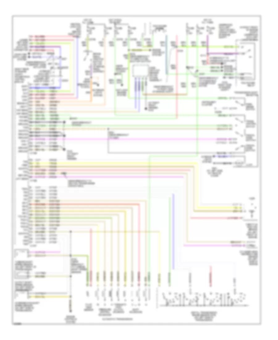
🚀 Welcome to the Launch of DiagnostData.com!

The new database is currently being populated with wiring diagrams up to 2024.

AUTOMOTIVE ELECTRICIANS PORTAL

TRANSMISSION – Ford Thunderbird 2005 – SYSTEM WIRING DIAGRAMS

TRANSMISSION

A/T Wiring Diagram for Ford Thunderbird 2005

AT Wiring Diagram for Ford Thunderbird 2005 https://portal-diagnostov.com/license.html
https://portal-diagnostov.com/license.html Automotive Electricians Portal FZCO Automotive Electricians Portal FZCO
Get access to all wiring diagrams of the carDownload PDF file

List of elements for A/T Wiring Diagram for Ford Thunderbird 2005:

  • (at right front fender) g103
  • (in right front of engine compt) underhood auxiliary junction box
  • (near breakout to defrost mode actuator)
  • (near breakout to g103)
  • (near breakout to g204) s218
  • (near breakout to ignition transformer capacitor 2)
  • (near breakout to right side of engine compt)
  • (right rear of engine compt) powertrain control module
  • (under
  • 15s-re21
  • 15s-re8
  • 29-re8
  • 29s-re13
  • 3/4
  • 31-re21
  • 31-re25
  • 31-re26
  • 31-re8
  • 4-ec7
  • 4-re8
  • 5-ec7
  • 5-re8
  • 7-re14
  • 7-rj28
  • 8-rj22
  • 8-rj28
  • 8-rj33
  • 8-rj39
  • 8-ta21
  • 8-ta26
  • 8-ta27
  • 8-ta37
  • 8-ta38
  • 8-ta39
  • 8-ta40
  • 8-ta51
  • 8-ta67
  • 8-ta68
  • 8-ta74
  • 9-re1
  • 9-re8
  • 9-rj22
  • 9-rj28
  • 9-ta1
  • 91-re27
  • 91s-ta23
  • 91s-ta24
  • 91s-ta47
  • 91s-ta63
  • 91s-ta64
  • 91s-ta65
  • 91s-ta69
  • 91s-ta70
  • Anti-lock brakes system
  • Automatic transmission
  • Brake in
  • Brake pedal position switch (on top of brake pedal support)
  • C175b
  • C175e
  • C175t
  • C220b
  • C270b
  • C270d
  • C270e
  • C283c
  • C283d
  • Can+
  • Can-
  • Central junction box (behind right kick panel)
  • Cht sens
  • Computer data lines system
  • Cylinder head temperature sensor (on left side of engine
  • Digital transmission range sensor (dtr) (on left side of transmission)
  • Dlc
  • Engine controls system
  • Exterior lights system
  • Fluid temp sensor
  • Fuse 15a
  • Fuse 30a
  • Fuse 5a
  • G102 (right side of engine compt)
  • G103 (at right front fender)
  • G301 (at left side of vehicle floor)
  • Ground
  • Hot at all times
  • Hot in run or start
  • Illum
  • Instrument cluster
  • Interior auxiliary junction box (under left side of dash)
  • Interior lights system
  • Intermediate shaft speed sensor (on left side of transmission)
  • Iss
  • Junction box)
  • Left side of dash) data link connector
  • Maf sens
  • Man +
  • Man -
  • Manual mode switch+
  • Manual mode switch-
  • Mass air flow sensor (on air intake assembly)
  • Motor)
  • Oss
  • Output shaft speed sensor (on left side of transmission)
  • Park sense switch
  • Pcm power diode
  • Pcm power relay
  • Pcs a
  • Pcs b
  • Pcs c
  • Power
  • Pressure control solenoids
  • Return
  • S100 (near breakout to g103)
  • S101
  • S102
  • S107
  • S109
  • S113
  • S122 (near breakout to turbine shaft speed sensor)
  • S126
  • S206
  • S207
  • S221 (near breakout to c264)
  • Scp+
  • Scp-
  • Shift solenoids
  • Sig rtn
  • Ss a
  • Ss b
  • Ss c
  • Ss d
  • Tcc sol
  • Tcs
  • Tft
  • Throttle position sensor (on left front of engine)
  • Torque conv clutch solenoid
  • Tps
  • Tr1
  • Tr2
  • Tr3a
  • Tr4
  • Trans control switch
  • Transmission shift selector
  • Tss
  • Turbine shaft speed sensor (on left front of transmission)
  • Underhood auxiliary junction box (in right front of engine compt)
  • Vbatt
  • Vref