AIR CONDITIONING
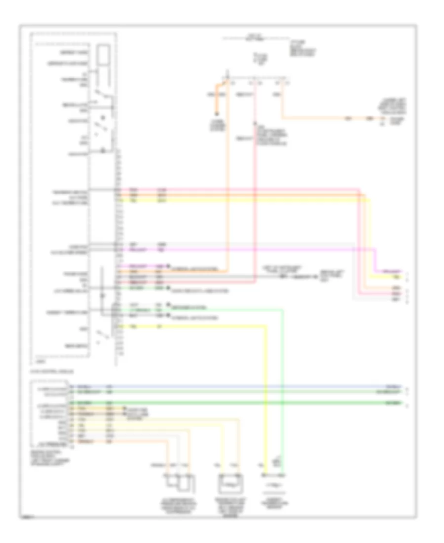
Automatic A/C Wiring Diagram (1 of 4) for GMC Acadia SLE 2007

List of elements for Automatic A/C Wiring Diagram (1 of 4) for GMC Acadia SLE 2007:
- (left of instrument panel air bag) j206
- (left of instrument panel cluster) j215
- (under left side of dash) body control module (bcm)
- 5v2
- A/c clutch
- A/c pressure
- A/c refrigerant pressure sensor (near rear of a/c compressor)
- Ambient temperature sensor
- Aux blower speed
- Aux mode
- Aux temperature
- Blower speed down
- Blower speed up
- Computer data lines system
- Defogger system
- Driver temp down
- Driver temp up
- Ect
- Engine control module (ecm) (left front corner of engine compt)
- Engine coolant temperature (ect) sensor (left side of engine)
- G301 (behind left kick panel)
- Gnd
- Headlamp ind
- Headlights system
- Hi spd bus +
- Hi spd bus -
- Hi spd clg fan
- Hot at all times
- Hvac control module
- Hvac fuse 15a
- I/p fuse block (behind right end of dash)
- Inside air temperature sensor
- Inside ambient (5v)
- J208 (in instrument panel harness, forward of floor console)
- J215
- Left ind
- Left solar load
- Lo spd clg fan
- Logic
- Low speed gmlan
- Mode down
- Mode pos
- Mode up
- Pnk
- Power mode
- Rear defog
- Right ind
- Right solar load
- Sunload sensor (under center of dash, near windshield defrost vent)
- Tan
- Temperature pos
- Upper left air temperature sensor (front left end of hvac module)
- Upper left vent (5v)
- Upper right air temperature sensor (front right end of hvac module)
- Upper right vent (5v)
- Wiper/ washer system
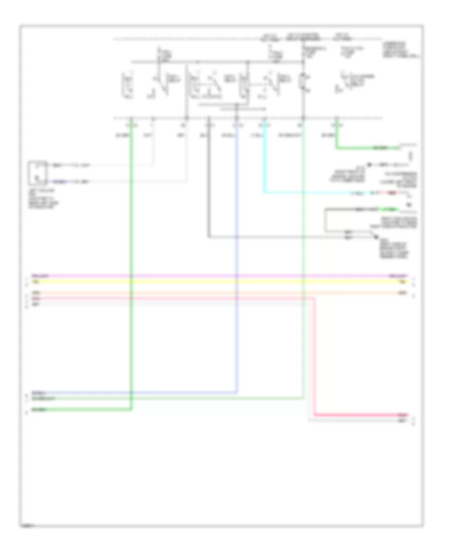
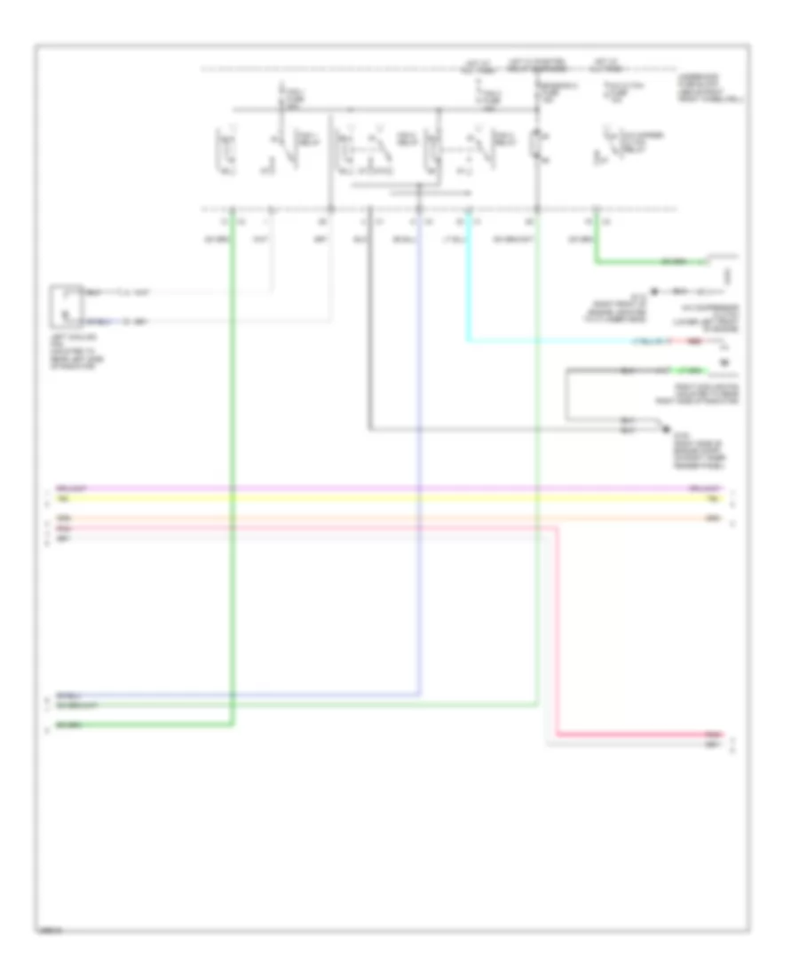
Automatic A/C Wiring Diagram (2 of 4) for GMC Acadia SLE 2007
List of elements for Automatic A/C Wiring Diagram (2 of 4) for GMC Acadia SLE 2007:
- 87a
- A/c cltch fuse 10a
- A/c cmprsr cltch relay
- A/c compressor clutch (lower left front of engine)
- Emission 2 fuse 15a
- Fan 1 fuse 30a
- Fan 1 relay
- Fan 2 fuse 40a
- Fan 2 relay
- Fan 3 relay
- G102 (right side of engine compt, on right inner fender panel)
- G110 (right front of engine, mounted to cylinder head)
- Hot at all times
- Hot w/ pwr/trn relay energized
- Left cooling fan (mounted to rear left side of radiator)
- Pnk
- Red
- Right cooling fan (mounted to rear right side of radiator)
- Underhood fuse block (above right front wheelwell)
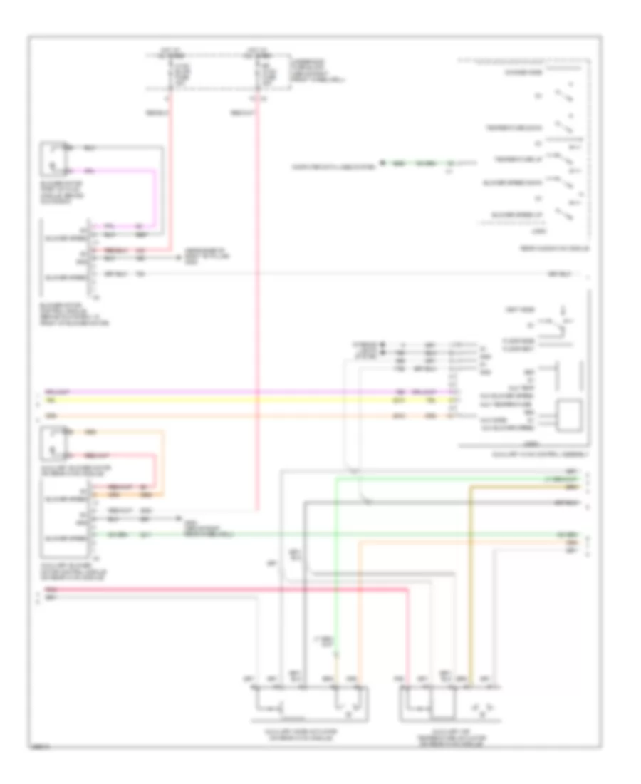
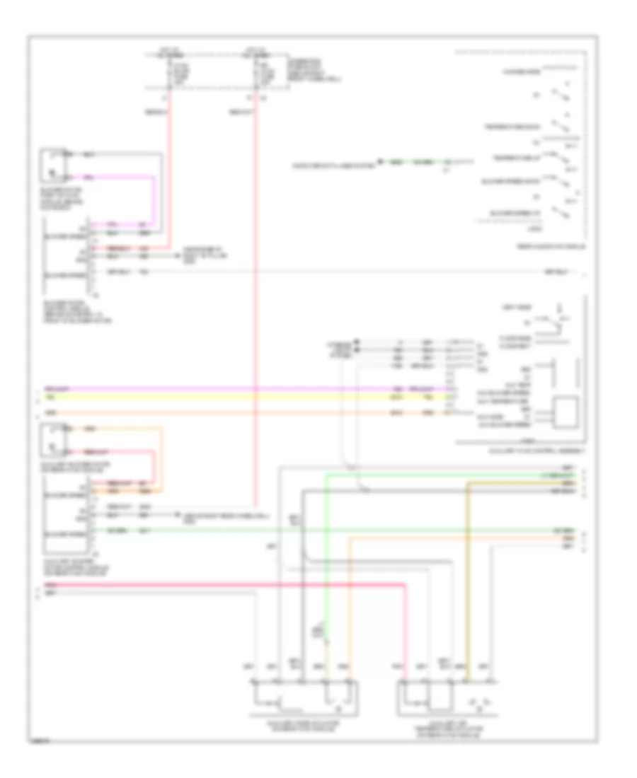
Automatic A/C Wiring Diagram (3 of 4) for GMC Acadia SLE 2007
List of elements for Automatic A/C Wiring Diagram (3 of 4) for GMC Acadia SLE 2007:
- (near base of right "b" pillar) g302
- Aux blower speed
- Aux mode
- Aux temp
- Aux temperature
- Auxiliary air temperature actuator (on rear hvac module)
- Auxiliary blower motor (on rear hvac module)
- Auxiliary blower motor control module (on rear hvac module)
- Auxiliary hvac control assembly
- Auxiliary mode actuator (on rear hvac module)
- Blower motor (part of hvac module, behind glove box)
- Blower motor control module (behind glove box, in front of blower motor)
- Blower speed
- Blower speed down
- Blower speed up
- Change mode
- Computer data lines system
- Floor mode
- Floor/vent
- G402 (above right rear wheelwell)
- Gnd
- Hot at all times
- Hvac blwr fuse 40a
- Interior lights system
- Logic
- Pnk
- Rear audio/hvac module
- Rr hvac fuse 30a
- Temperature down
- Temperature up
- Underhood fuse block (above right front wheelwell)
- Vent mode
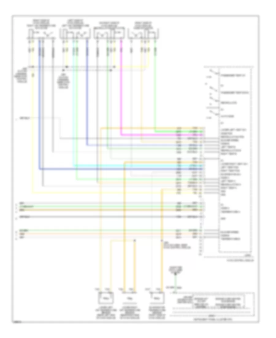
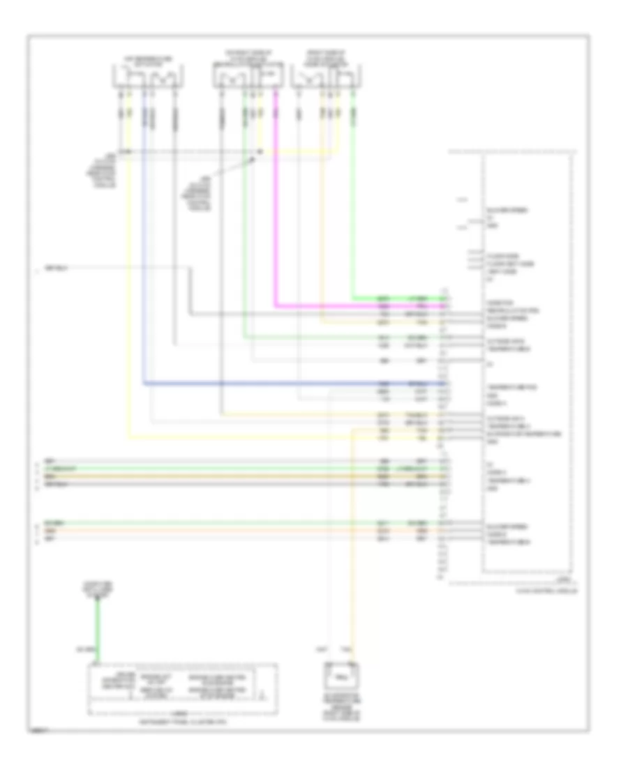
Automatic A/C Wiring Diagram (4 of 4) for GMC Acadia SLE 2007
List of elements for Automatic A/C Wiring Diagram (4 of 4) for GMC Acadia SLE 2007:
- (left side of hvac module) left air temperature actuator
- (on right side of hvac module) recirculation actuator
- (right side of hvac module) mode actuator
- (right side of hvac module) right air temperature actuator
- Auto mode
- Blower speed
- Computer data lines system
- Driver information center (dic)
- Engine hot a/c off
- Engine over heated idle engine
- Engine over heated stop engine
- Evaporator (5v)
- Evaporator temperature sensor (right side of hvac module)
- Gnd
- Hvac control module
- Instrument panel cluster (ipc)
- J260 (in hvac harness, near hvac control module)
- J262 (in hvac harness, near hvac control module)
- J264 (in hvac harn, near hvac control module)
- Left temp a
- Left temp b
- Left temp pos
- Logic
- Lower left air temperature sensor (rear left end of hvac module)
- Lower left vent (5v)
- Lower right air temperature sensor (rear right end of hvac module)
- Lower right vent (5v)
- Mode a
- Mode b
- Mode pos
- Passenger temp down
- Passenger temp up
- Recirculate
- Recirculation a
- Recirculation b
- Recirculation pos
- Right temp a
- Right temp b
- Right temp pos
- Service a/c system
- Tan
- Temperature a
- Temperature b
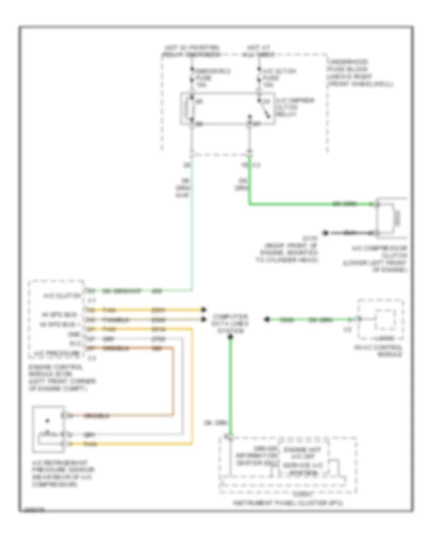
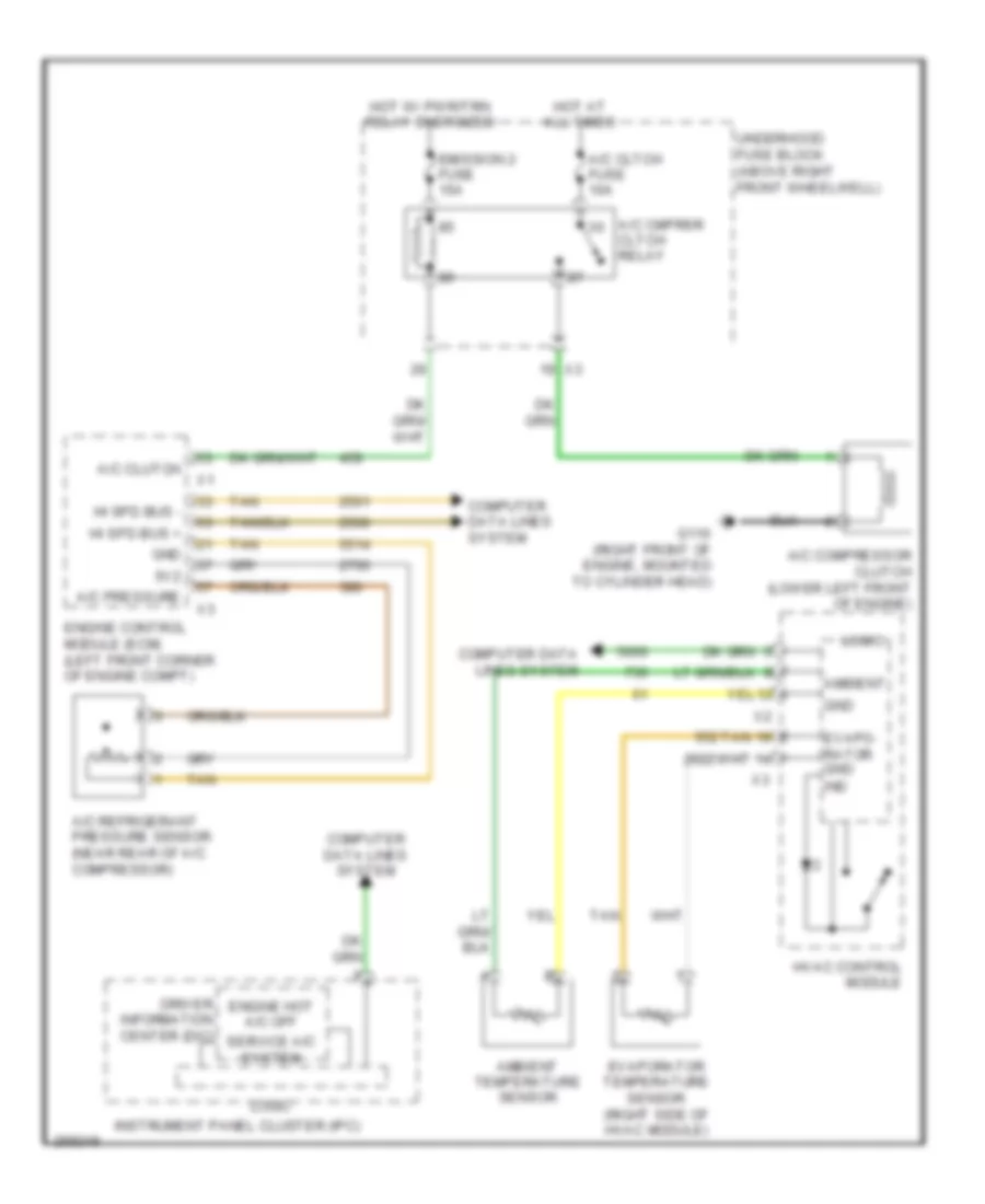
Compressor Wiring Diagram, with Auto A/C for GMC Acadia SLE 2007
List of elements for Compressor Wiring Diagram, with Auto A/C for GMC Acadia SLE 2007:
- 5v2
- A/c cltch fuse 10a
- A/c clutch
- A/c cmprsr cltch relay
- A/c compressor clutch (lower left front of engine)
- A/c pressure
- A/c refrigerant pressure sensor (near rear of a/c compressor)
- Computer data lines system
- Driver information center (dic)
- Emission 2 fuse 15a
- Engine control module (ecm) (left front corner of engine compt)
- Engine hot a/c off
- G110 (right front of engine, mounted to cylinder head)
- Gnd
- Hi spd bus +
- Hi spd bus -
- Hot at all times
- Hot w/ pwr/trn relay energized
- Hvac control module
- Instrument panel cluster (ipc)
- Logic
- Service a/c system
- Tan
- Underhood fuse block (above right front wheelwell)
Compressor Wiring Diagram, with Manual A/C for GMC Acadia SLE 2007
List of elements for Compressor Wiring Diagram, with Manual A/C for GMC Acadia SLE 2007:
- 5v2
- A/c cltch fuse 10a
- A/c clutch
- A/c cmprsr cltch relay
- A/c compressor clutch (lower left front of engine)
- A/c pressure
- A/c refrigerant pressure sensor (near rear of a/c compressor)
- Ambient
- Ambient temperature sensor
- Computer data lines system
- Driver information center (dic)
- Emission 2 fuse 15a
- Engine control module (ecm) (left front corner of engine compt)
- Engine hot a/c off
- Evapo- rator gnd ind
- Evaporator temperature sensor (right side of hvac module)
- G110 (right front of engine, mounted to cylinder head)
- Gnd
- Hi spd bus +
- Hi spd bus -
- Hot at all times
- Hot w/ pwr/trn relay energized
- Hvac control module
- Instrument panel cluster (ipc)
- Logic
- Service a/c system
- Tan
- Underhood fuse block (above right front wheelwell)
Manual A/C Wiring Diagram (1 of 4) for GMC Acadia SLE 2007
List of elements for Manual A/C Wiring Diagram (1 of 4) for GMC Acadia SLE 2007:
- (behind left kick panel) g301
- (left of instrument panel cluster) j215
- (under left side of dash) body control module (bcm)
- 5v2
- A/c
- A/c clutch
- A/c pressure
- A/c refrigerant pressure sensor (near rear of a/c compressor)
- Ambient temperature sensor
- Ambient teperature
- Aux blower speed
- Aux mode
- Aux temperature
- Computer data lines system
- Defogger system
- Defrost mode
- Defrost/floor mode
- Ect
- Engine control module (ecm) (left front corner of engine compt)
- Engine coolant temperature (ect) sensor (left side of engine)
- Gnd
- Hi spd clg fan
- Hi spd data +
- Hi spd data -
- Hot at all times
- Hvac control module
- Hvac fuse 15a
- I/p fuse block (behind right end of dash)
- Indicator
- Interior lights system
- J208 (in instrument panel harness, forward of floor console)
- Lo spd clg fan
- Logic
- Low speed gmlan
- Mode pos
- Pnk
- Power mode
- Rear defog
- Recirculate
- Tan
- Temperature
- Temperature pos
- Wiper/ washer system
Manual A/C Wiring Diagram (2 of 4) for GMC Acadia SLE 2007
List of elements for Manual A/C Wiring Diagram (2 of 4) for GMC Acadia SLE 2007:
- 87a
- A/c cltch fuse 10a
- A/c cmprsr cltch relay
- A/c compressor clutch (lower left front of engine)
- Emission 2 fuse 15a
- Fan 1 fuse 30a
- Fan 1 relay
- Fan 2 fuse 40a
- Fan 2 relay
- Fan 3 relay
- G102 (right side of engine compt, on right inner fender panel)
- G110 (right front of engine, mounted to cylinder head)
- Hot at all times
- Hot w/ pwr/trn relay energized
- Left cooling fan (mounted to rear left side of radiator)
- Pnk
- Red
- Right cooling fan (mounted to rear right side of radiator)
- Underhood fuse block (above right front wheelwell)
Manual A/C Wiring Diagram (3 of 4) for GMC Acadia SLE 2007
List of elements for Manual A/C Wiring Diagram (3 of 4) for GMC Acadia SLE 2007:
- (above right rear wheelwell) g402
- (near base of right "b" pillar) g302
- Aux blower speed
- Aux mode
- Aux temp
- Aux temperature
- Auxiliary air temperature actuator (on rear hvac module)
- Auxiliary blower motor (on rear hvac module)
- Auxiliary blower motor control module (on rear hvac module)
- Auxiliary hvac control assembly
- Auxiliary mode actuator (on rear hvac module)
- Blower motor (part of hvac module, behind glove box)
- Blower motor control module (behind glove box, in front of blower motor)
- Blower speed
- Blower speed down
- Blower speed up
- Change mode
- Computer data lines system
- Floor mode
- Floor/vent
- Gnd
- Hot at all times
- Hvac blwr fuse 40a
- Interior lights system
- Logic
- Pnk
- Rear audio/hvac module
- Rr hvac fuse 30a
- Temperature down
- Temperature up
- Underhood fuse block (above right front wheelwell)
- Vent mode
Manual A/C Wiring Diagram (4 of 4) for GMC Acadia SLE 2007
List of elements for Manual A/C Wiring Diagram (4 of 4) for GMC Acadia SLE 2007:
- (on right side of hvac module) recirculation actuator
- (right side of hvac module) mode actuator
- Air temperature actuator
- Blower speed
- Computer data lines system
- Driver information center (dic)
- Engine hot a/c off
- Engine over heated idle engine
- Engine over heated stop engine
- Evaporator temperature
- Evaporator temperature sensor (right side of hvac module)
- Floor mode
- Floor/vent mode
- Gnd
- Hvac control module
- Instrument panel cluster (ipc)
- J260 (in hvac harness, near hvac control module)
- J262 (in hvac harness, near hvac control module)
- Logic
- Mode a
- Mode b
- Mode pos
- Outside air a
- Outside air b
- Recirculation pos
- Service a/c system
- Tan
- Temperature a
- Temperature b
- Temperature pos
- Vent mode