AIR CONDITIONING
Compressor Wiring Diagram for GMC Sonoma 2004

List of elements for Compressor Wiring Diagram for GMC Sonoma 2004:
- (engine harness, between breakouts to rear heated oxygen sensors connector & body harness connector, 7 cm from breakout to heated oxygen sensor connector) s106
- (rear of right cylinder head) g102
- (rear of right cylinder head) g103
- A/c
- A/c comp rly ctrl
- A/c compressor clutch
- A/c compressor clutch diode
- A/c compressor clutch relay
- A/c fuse 10a
- A/c high pressure switch (on rear of a/c compressor)
- A/c low pressure switch (at a/c accumulator)
- A/c low sw signal
- A/c request signal
- Bi-level a/c
- Blend
- D12
- Defrost
- Heat
- Hot at all times
- Hot in run
- Hot in run & start
- Hvac control assembly
- Hvac fuse 9 20a
- I/p fuse block (on left end of dash)
- Ign e fuse 10a
- Max a/c
- Nca
- Off
- Powertrain control module (pcm) (on right side of engine compartment)
- S103 (engine harn, 19.5 cm from throttle position sensor)
- Underhood fuse block (on top of left front inner wheelwell)
- Vent
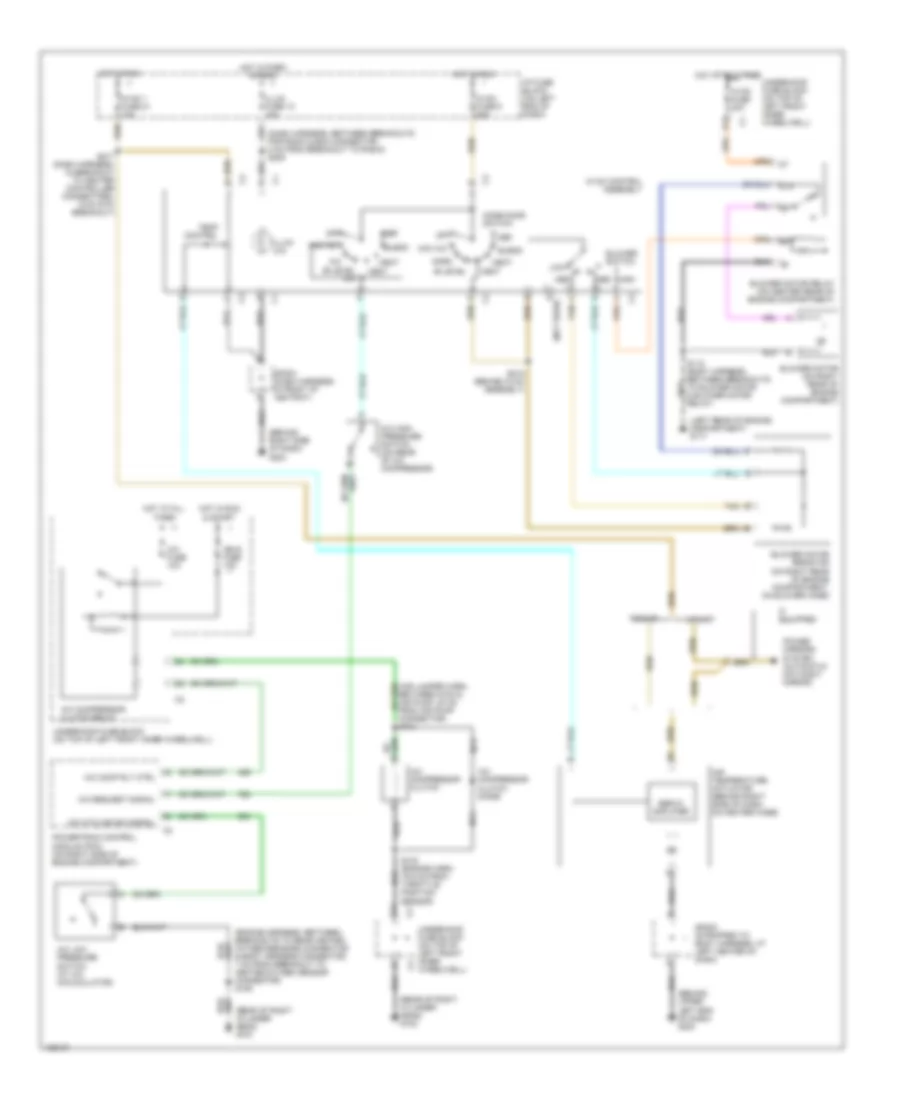
Manual A/C Wiring Diagram for GMC Sonoma 2004
List of elements for Manual A/C Wiring Diagram for GMC Sonoma 2004:
- (behind right side of dash) g203
- (behind upper left end of dash) g200
- (dash harness, between breakouts for radio & bcm connector 8 cm from breakout to radio) s205
- (engine harness, between breakouts to rear heated oxygen sensors connector & body harness connector, 7 cm from breakout to heated oxygen sensor connector) s106
- (left rear of engine compartment) g117
- (rear of right cylinder head) g102
- (rear of right cylinder head) g103
- 87a
- A/c
- A/c comp rly ctrl
- A/c compressor clutch
- A/c compressor clutch diode
- A/c compressor clutch relay
- A/c cycling sw signal
- A/c fuse 10a
- A/c high pressure switch (on rear of a/c compressor)
- A/c low pressure switch (at a/c accumulator)
- A/c request signal
- Air temperature actuator (behind right side of dash, on heater case)
- Bi-level
- Bi-level a/c
- Blend
- Blower motor (on right rear of engine compartment)
- Blower motor relay (on center rear of engine compartment)
- Blower motor resistor (on right rear of engine compartment, on blower case)
- Blower switch
- Connector) s104
- D (not used)
- D12
- Def
- Heat
- High
- Hot at all times
- Hot in park & head
- Hot in run
- Hot in run & start
- Hvac 1 fuse 21 10a
- Hvac control assembly
- Hvac fuse 30a
- Hvac fuse 9 20a
- I/p fuse block (on left end of dash)
- If equipped
- Ign e fuse 10a
- Illum (x4)
- Illum fuse 12 10a
- Low
- Max a/c
- Med
- Mode door switch
- Nca
- Norm
- Off
- Pickup
- Power mirrors system (automatic day/night mirror)
- Powertrain control module (pcm) (on right side of engine compartment)
- S103 (engine harn, 19.5 cm from throttle position sensor)
- S118 (body harness, between breakouts to blower motor & blower motor relay)
- S215 (behind hvac assembly)
- S217 (dash harness, in breakout to heater controller connectors, 6 cm into breakout)
- Servo amplifier
- Sp202 (strapped to body harness, at left center of dash)
- Sp203 (dash harness, in front of ashtray)
- Tan
- Temp control
- Underhood fuse block (on top of left front inner wheelwell)
- Utility
- Vent
 English