AIR CONDITIONING
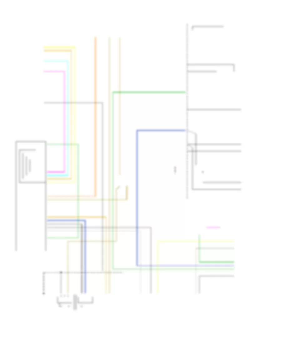
Compressor Wiring Diagram for Pontiac Aztek GT 2001

List of elements for Compressor Wiring Diagram for Pontiac Aztek GT 2001:
- +5v reference
- A/c compressor clutch
- A/c clu fuse 10a
- A/c compressor clutch relay
- A/c compressor diode
- A/c press sig
- A/c refrigerent pressure sensor (left side of engine compt, on accumulator)
- A/c request
- A10
- B10
- Battery
- Body control module (attached to console wiring j/b)
- Comp control
- Console accessory wiring junction block
- Datalink connector (below steering column)
- G114 (left rear of engine)
- G201 (behind right side of dash)
- Ground
- Hot at all times
- Hot in run or start
- Hvac control assembly
- Ign 1 main relay (closed in run or start)
- Ign hvac fuse 10a
- Ignition
- Ip misc fuse 10a c1
- Low reference
- Powertrain control module (left side of engine compartment, in air cleaner assembly)
- Resistor breakout)
- Serial data
- Splice pack sp250
- Star connector (behind dash)
- Underhood fuse block (right side of engine compt, above battery)
Manual A/C Wiring Diagram for Pontiac Aztek GT 2001
List of elements for Manual A/C Wiring Diagram for Pontiac Aztek GT 2001:
- (dash harn, 4 cm from blwr motor resistor breakout) s213
- (fuel inj harn, top center of engine)
- (fwd lamp harn, 5 cm from horn breakout)
- +5v reference
- A/c compressor clutch
- A/c clu fuse 10a
- A/c compressor clutch relay
- A/c compressor diode
- A/c press signal
- A/c refrigerent pressure sensor (left side
- A/c request
- A/c request sig
- A10
- B10
- Battery
- Blower motor
- Blower motor relay
- Blower motor resistor assembly
- Blower sw off
- Body control module (attached to console wiring j/b)
- Breakout)
- C11
- Comp control
- Console accessory wiring junction block
- Cool fan 1 fuse 30a
- Cool fan 1 relay
- Cool fan 2 fuse 30a
- Cool fan 2 relay
- Cool fan 3 relay
- Coolant fan 1
- Coolant fan 2
- Datalink connector (below steering column)
- Defogger
- Ect sensor
- Engine controls sensor (map sensor)
- Engine coolant temperature (ect) sensor (top rear of engine, near thermostat housing)
- Engine cooling fan (left)
- Engine cooling fan (right)
- F10
- Frost sens +
- Frost sens rtn
- Frost sensor (in hvac assembly, on evap coil)
- Frt blwr fuse 25a
- G103 (right side of engine compt)
- G114 (left rear of engine)
- G201 (behind right side of dash)
- Ground
- Hot at all times
- Hot in run
- Hot in run or start
- Hvac control assembly
- Ign 1 main relay (closed in run or start)
- Ign 3 fuse 40a
- Ign hvac fuse 10a c1
- Ignition
- Interior lights
- Ip misc fuse 10a
- Lamp dim sig
- Left air temp act
- Left air temperature motor (left side of hvac assembly)
- Low reference
- Mode door ctrl
- Mode motor (left side of hvac assembly)
- Of engine compt, on accumulator)
- Off
- Powertrain control module (left side of engine compartment, in air cleaner assembly)
- Rear defog
- Recir/osa motor (right end of hvac assembly)
- Recirc door ctrl
- Red
- Right air temp act
- Right air temperature mptpr (left side of hvac assembly
- S105
- S110
- S123
- Serial data
- Splice pack sp250
- Star connector (behind dash)
- Tan
- Underhood fuse block (right side of engine compt, above battery)