AIR CONDITIONING
Compressor Wiring Diagram for Pontiac Sunfire 2003

List of elements for Compressor Wiring Diagram for Pontiac Sunfire 2003:
- (engine harn, 13 cm from cooling fan conn breakout) pnk
- (left front of engine compt)
- 5 volt ref
- A/c comp clutch rly
- A/c compressor clutch
- A/c compressor clutch diode (in a/c compressor clutch connector breakout)
- A/c compressor clutch relay
- A/c fuse 10a
- A/c press sens sig
- A/c refrigerant pressure sensor (right front corner of engine compt, on a/c refrigerant line)
- A20
- A22
- B20
- B22
- Compressor clutch conn)
- Erls fuse 10a
- G112 (on rear of engine)
- Hot at all times
- Hot in run, bulb test or start
- I/p fuse block (behind lower left side of dash)
- Low ref
- Pnk
- Powertrain control module (pcm) (on right rear of engine compartment)
- S107
- S110 (engine harn, near a/c compressor clutch conn)
- Underhood fuse block
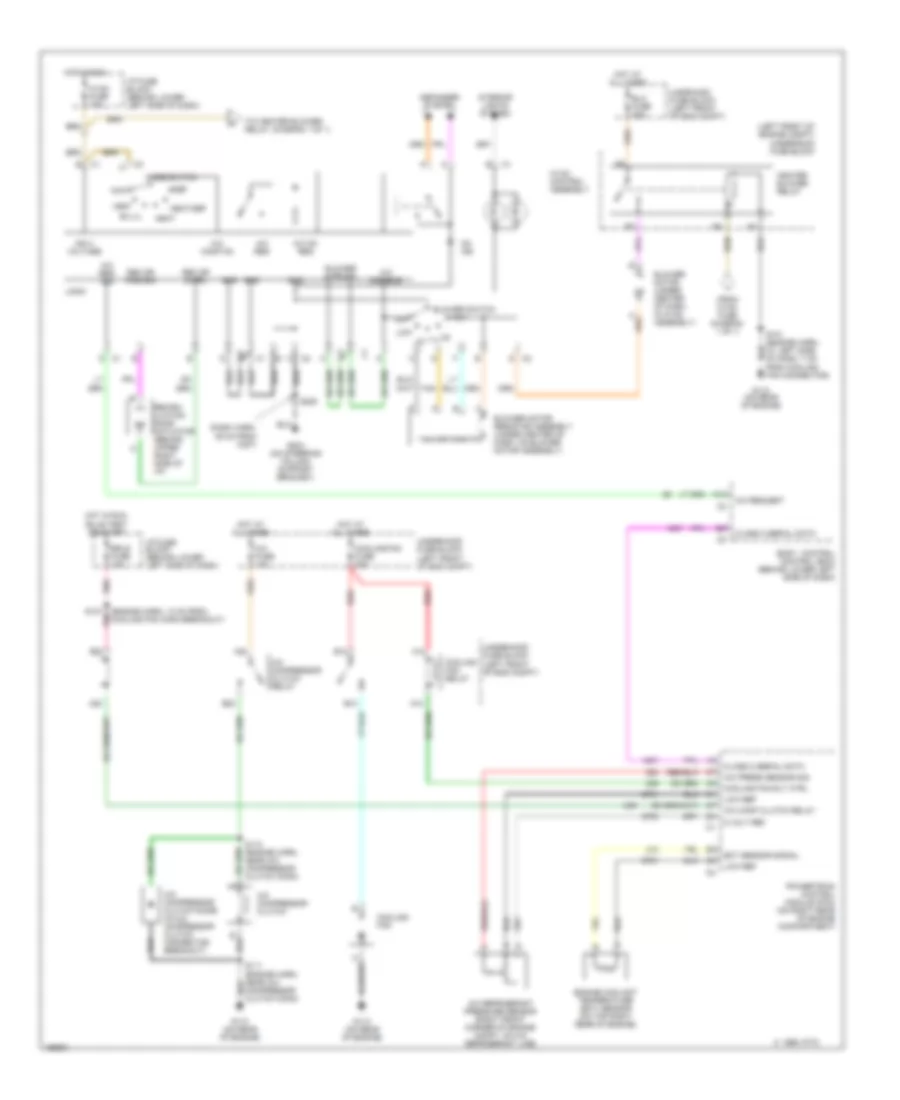
Manual A/C Wiring Diagram for Pontiac Sunfire 2003
List of elements for Manual A/C Wiring Diagram for Pontiac Sunfire 2003:
- (dash harn, 39 cm from c207)
- (engine harn, 13 cm from
- (from hvac fuse diagram 1 of 1)
- (left front of eng compt)
- (left front of engine compt)
- (to heater blower relay, diagram 1 of 1)
- 5 volt ref
- A/c comp clutch relay
- A/c comp on
- A/c compressor clutch
- A/c compressor clutch diode (in a/c compressor clutch connector breakout)
- A/c compressor clutch relay
- A/c disable
- A/c fuse 10a
- A/c on req
- A/c press sensor sig cooling fan rly ctrl
- A/c refrigerant pressure sensor (right front corner of engine compt, on a/c refrigerant line)
- A/c req
- A/c req sig
- A/c request
- A10
- A12
- A20
- A22
- B10
- B12
- B20
- B22
- Bi-lvl
- Blo fuse 30a
- Blower motor (under center of dash, in hvac assembly)
- Blower motor resistor assembly (under center of dash, on blower motor assembly)
- Blower mtr off
- Blower switch
- Body control control (bcm) (behind lower left side of dash)
- C 1995 vftc
- Class 2 serial data
- Compressor clutch conn)
- Cooling fan
- Cooling fan fuse 30a
- Cooling fan relay
- Def
- Defogger system
- Ect sensor signal
- Engine coolant temperature (ect) sensor (on top right rear of engine)
- Erls fuse 10a
- F c3
- G112 (on rear of engine)
- G204 (on steering column support bracket)
- Gnd
- H c3
- Heat
- Heat/def
- Heater blower relay
- High
- Hot at all times
- Hot in run
- Hot in run, bulb test or start
- Hvac control assembly
- Hvac fuse 10a
- I/p fuse block (behind lower left side of dash)
- Ign 3 voltage
- Interior lights system
- Logic
- Low
- Low ref
- Max
- Mode switch
- Off
- On ind
- Pnk
- Powertrain control module (pcm) (on right rear of engine compartment)
- Rec dr cntrl
- Rec dr pos sig
- Recirc- ulation door actuator (behind upper right side of i/p)
- Red
- S101 (engine harn, at left side of dash, 7 cm from cooling fan connector)
- S107 pnk cooling fan conn breakout)
- S110 (engine harn, near a/c compressor clutch conn)
- S205
- Tan
- Underhood fuse block
- Undrhood fuse block (left front of eng compt)
- Vent