AIR CONDITIONING
Compressor Wiring Diagram for Pontiac Vibe 2004

List of elements for Compressor Wiring Diagram for Pontiac Vibe 2004:
- (behind right body hinge pillar trim panel)
- A/c compressor clutch (at left front of engine)
- A/c compressor clutch relay
- A/c fuse 10a
- A/c resistor (behind right side of dash)
- C13
- Clutch rly ctrl
- Evap temp sens gnd
- Evap temp sens in
- G201
- Heater fuse 40a
- Heater relay
- Hot at all times
- Instrument panel fuse block (left of steering column, behind storage compartment)
- Manual a/c circuit
- Powertrain control module (pcm) (behind right side of dash)
- Right instrument panel junction block (behind right side of dash)
- Sp108 (in engine accessory harness, near pcm)
- Sp201
- Underhood fuse block (left side of engine compartment, mounted to inner fender)
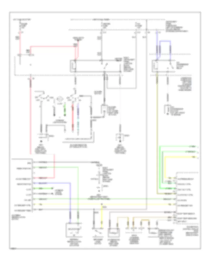
Manual A/C Wiring Diagram (1 of 2) for Pontiac Vibe 2004
List of elements for Manual A/C Wiring Diagram (1 of 2) for Pontiac Vibe 2004:
- (behind right body hinge pillar trim panel)
- A/c compressor clutch (at left front of engine)
- A/c compressor clutch relay
- A/c fresh recirculation switch
- A/c fuse 10a
- A/c led
- A/c on sig
- A/c pressure sw
- A/c request ctrl
- A/c request feed
- A/c request sig
- A/c resistor (behind right side of dash)
- A/c sw feed ckt
- Blower motor (at lower right side of hvac)
- Blower resistor (at middle of hvac)
- Blower switch
- C13
- Clutch rly ctrl
- Defogger mode switch
- Ect input
- Engine coolant temperature (ect) sensor (1.8l (vin l): at rear of engine) (1.8l (vin 8): at left side of cylinder head)
- Evap temp sens gnd
- Evap temp sens in
- Fan 1 rly ctrl
- Fan 2 rly ctrl
- Fresh position
- G201
- Gauge fuse 10a
- Gnd
- Headlights system
- Heater fuse 40a
- High
- Hot at all times
- Hot in on or start
- Illum
- Instrument panel fuse block (left of steering column, behind storage compartment)
- Interior lights system
- Low
- Off
- Powertrain control module (pcm) (behind right side of dash)
- Recir position
- Red
- Refresh/ recirculation air inlet actuator
- Right heater instrument relay panel junction block (behind right side of dash)
- Right instrument panel junction c3 block (behind right side of dash)
- S223
- S224
- S225
- Solid state
- Sp108 (in engine accessory harness, near pcm)
- Sp201
- Underhood fuse block (left side of engine compartment, mounted to inner fender)
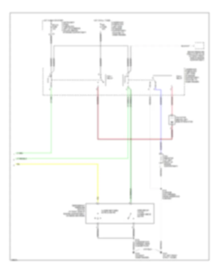
Manual A/C Wiring Diagram (2 of 2) for Pontiac Vibe 2004
List of elements for Manual A/C Wiring Diagram (2 of 2) for Pontiac Vibe 2004:
- Brake pressure modulator valve (at right front side of engine compartment)
- Closed between 28 psi & 455 psi
- Ecu-ig fuse 10a
- Fan 1 relay
- Fan 2 relay
- Fan motor (behind left side of radiator)
- Fan resistor (at left front of engine compartment)
- G102 (on right inner fender)
- G103 (at left front strut tower)
- Hot at all times
- Hot in run or start
- Instrument panel fuse block (left of steering column, behind storage compartment)
- Open below 178 psi closed above 220 psi
- Rdi fuse 40a
- Refrigerant pressure switch (at right side of engine compartment, on receiver drier)
- S102 (in engine main harness, near washer pump)
- S103 (in engine main harness, inside underhood fuse box)
- Underhood fuse block (left side of engine compartment, mounted to inner fender)