AIR CONDITIONING
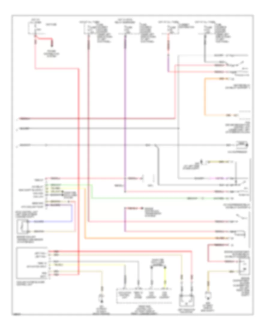
Automatic A/C Wiring Diagram (1 of 2) for Porsche Cayman 2008

List of elements for Automatic A/C Wiring Diagram (1 of 2) for Porsche Cayman 2008:
- +5v
- Can comfort high
- Can comfort low
- Central flap
- Central flap recir- culation drive motor
- Circulating air/ outside air flap motor
- Climatronic control unit
- Close circ air
- Compressor volt
- Computer data lines system
- Cool
- Cooling water pressure sensor
- Defrost
- Exhaust airflow space sensor
- Fan actuation
- Fan outlet sensor
- Fan return
- Fan return (+)
- Final stage
- Footwell
- Footwell/def flap
- Footwell/defrost
- Footwell/defrost flap drive motor
- Fresh air blower
- Fuse f2 7.5a
- Fuse holder c (on fuse support, under left side of dash, at left kick panel)
- Gp5 (at right side of dash)
- Hot
- Hot w/ term 15 relay energized
- Intake air climate sensor
- Middle level
- Open (fresh air)
- Outside air flap
- Outside sensor
- Red
- Sensor gnd
- Sun sensor
- Temperature flap
- Temperature valve drive motor
- Term 15
- Term 30
- Term 31
- Water press sens
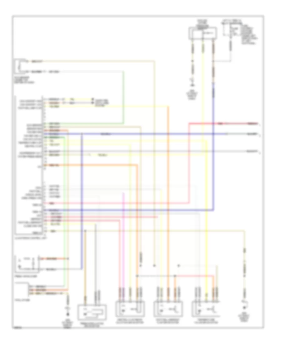
Automatic A/C Wiring Diagram (2 of 2) for Porsche Cayman 2008
List of elements for Automatic A/C Wiring Diagram (2 of 2) for Porsche Cayman 2008:
- 80a
- A/c compressor
- A/c compressor relay (on relay support 2)
- A/c relay
- A21
- Actuation control unit
- Actuation input
- Batt
- Can high
- Can high comfort
- Can low
- Can low comfort
- Computer data lines system
- Cooling water blower control unit
- Current distribution
- Dmtl
- Eng compt blwr rly
- Engine compartment blower (cleaner fan) (on left front side of eng compt)
- Engine compartment blower relay (on relay support 2)
- Engine controls & transmission systems
- Engine coolant temperature sensor (in water box)
- Front end control unit (at right side of front luggage compt)
- Fuse f1 15a
- Fuse f10 25a
- Fuse f5 25a
- Fuse f6 80a
- Fuse holder b (on fuse support, under left side of dash, at left kick panel)
- Fuse holder d (on fuse support, under left side of dash, at left kick panel)
- Fuse holder f (on fuse support, under left side of dash, at left kick panel)
- Gnd
- Gp1 (in front of right front fender)
- Gp8 (at left side of eng compt)
- Gp9 (at right side of eng compt)
- Heater relay (on relay support 1)
- Hot at all times
- Hot w/ mfi-di relay energized
- Left fan +
- Left fan -
- Left radiator fan motor
- Mfi-di control unit (left side of rear luggage compt)
- Midi fuse
- Nca
- Ntc coolant pump
- Pas (driver recognition) control unit (under dash, left of steering column)
- Power distribution system
- Red
- Sens gnd
- Term 15
- Term 15 final stage
- Term 87
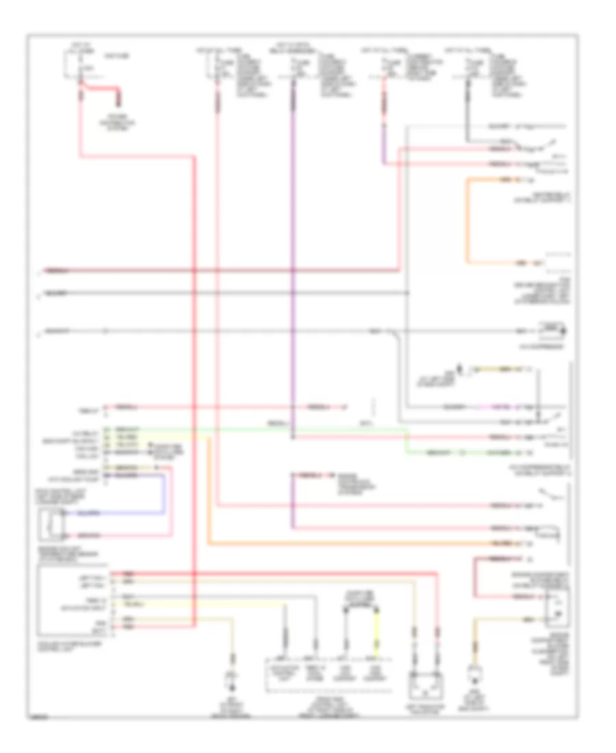
Manual A/C Wiring Diagram (1 of 2) for Porsche Cayman 2008
List of elements for Manual A/C Wiring Diagram (1 of 2) for Porsche Cayman 2008:
- +5v
- Can comfort high
- Can comfort low
- Central flap
- Central flap recir- culation drive motor
- Climatronic control unit
- Close circ air
- Compressor volt
- Computer data lines system
- Cool
- Cooling water pressure sensor
- Defrost
- Fan actuation
- Fan return
- Fan return (+)
- Final stage
- Footwell
- Footwell/def flap
- Footwell/defrost
- Footwell/defrost flap drive motor
- Fresh air blower
- Fresh/circulating drive motor
- Fuse f2 7.5a
- Fuse holder c (on fuse support, under left side of dash, at left kick panel)
- Gp5 (at right side of dash)
- Hot
- Hot w/ term 15 relay energized
- Middle level
- Open (fresh air)
- Red
- Sensor gnd
- Sun sensor
- Sun sensor (under top center of dash)
- Temperature flap
- Temperature valve drive motor
- Term 15
- Term 30
- Term 31
- Water press sens
Manual A/C Wiring Diagram (2 of 2) for Porsche Cayman 2008
List of elements for Manual A/C Wiring Diagram (2 of 2) for Porsche Cayman 2008:
- 80a
- A/c compressor
- A/c compressor relay (on relay support 2)
- A/c relay
- A15
- A21
- Actuation control unit
- Actuation input
- B42
- Batt
- Can high
- Can high comfort
- Can low
- Can low comfort
- Computer data lines system
- Cooling water blower control unit
- Current distribution (behind right side of dash)
- Dmtl
- Eng compt blwr rly
- Engine compartment blower (cleaner fan) (on left front side of eng compt)
- Engine compartment blower relay (on relay support 2)
- Engine controls & transmission systems
- Engine coolant temperature sensor (in water box)
- Front end control unit (at right side of front luggage compt)
- Fuse f1 15a
- Fuse f10 25a
- Fuse f5 25a
- Fuse f6 80a
- Fuse holder b (on fuse support, under left side of dash, at left kick panel)
- Fuse holder d (on fuse support, under left side of dash, at left kick panel)
- Fuse holder f (on fuse support, under left side of dash, at left kick panel)
- Gnd
- Gp1 (in front of right front fender)
- Gp8 (at left side of eng compt)
- Gp9 (at left side of eng compt)
- Heater relay (on relay support 1)
- Hot at all times
- Hot w/ mfi-di relay energized
- Left fan +
- Left fan -
- Left radiator fan motor
- Mfi-di control unit (left side of rear luggage compt)
- Midi fuse
- Nca
- Ntc coolant pump
- Pas (driver recognition) control unit (under dash, left of steering column)
- Power distribution system
- Red
- Sens gnd
- Term 15
- Term 15 final stage
- Term 87