ANTI-LOCK BRAKES
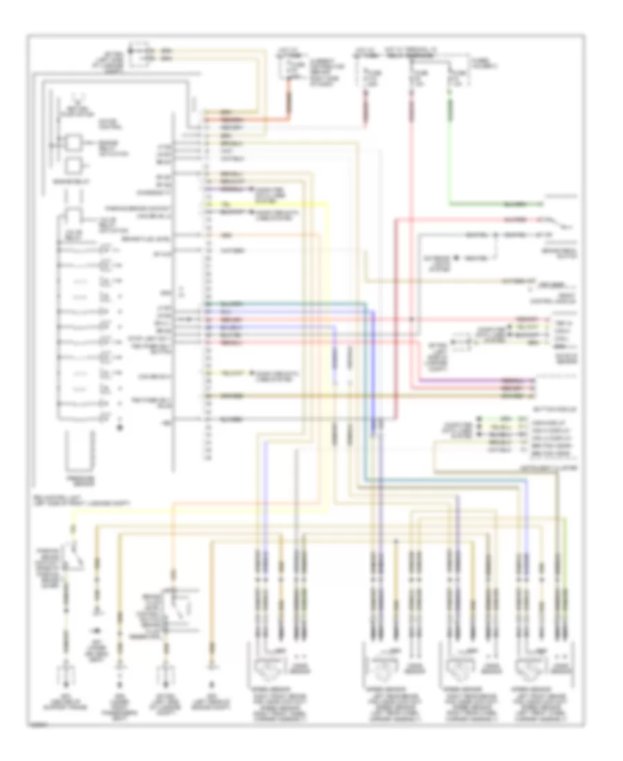
Anti-lock Brakes Wiring Diagram for Porsche 911 Carrera 4 2010
List of elements for Anti-lock Brakes Wiring Diagram for Porsche 911 Carrera 4 2010:
- +bs
- Brake fluid level
- Brake fluid level control switch (brake fluid reservoir)
- Brake pedal switch
- Brk pad wear
- Brk pad wear+
- Button module
- Can drive hi
- Can drive lo
- Can hi display
- Can lo display
- Can-h
- Can-l
- Canwake up
- Carrier assembly)
- Computer data lines system
- Current distributor (behind right side of dash)
- Df alr
- Diagnosis "k"
- Engine relay
- Engine relay actuation
- Exterior lights system
- Front control module
- Fuse f10 25a
- Fuse f4 10a
- Fuse f5 50a
- Fuse f8 10a
- Fuses holder c
- Gnd
- Gp psm (left side of luggage compt)
- Gp4 (center of support frame)
- Gp6 (under front passenger's seat)
- Gp7 (under driver's seat)
- Gp8 (left rear of engine compt)
- Hot at all times
- Hot w/ terminal 15 relay energized
- Instrument cluster
- Left front brake pad wear contact/ speed sensor (left front wheel
- Left rear brake pad wear contact/ speed sensor (left rear wheel
- Lf dp
- Lf ds
- Lr dp
- Lr ds
- Motor control
- Nca
- Parking brake contact
- Parking brake contact (base of parking brake lever)
- Pressure sensor
- Psm control unit (left side of front luggage compt)
- Psm passively bulb
- Psm passively button
- Rate of sensor
- Return pump motor
- Rf dp
- Rf ds
- Right front brake pad wear contact/ speed sensor (right front wheel carrier assembly)
- Right rear brake pad wear contact/ speed sensor (right rear wheel
- Rr dp
- Rr ds
- Spd sens
- Speed sensor
- Spl4 +
- Stop light sw +
- Ter 15
- Valve relay
- Valve relay actuation
- Wear sensor
 English