ANTI-LOCK BRAKES
Anti-lock Brakes Wiring Diagram, with Stability Assist, Early Production for Porsche 911 GT3 2005

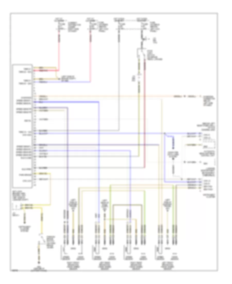
List of elements for Anti-lock Brakes Wiring Diagram, with Stability Assist, Early Production for Porsche 911 GT3 2005:
- (front of brake booster) pre-charging pump
- (left rear of passenger compt)
- (left side of support frame) gp3
- (on steering column) steering angle sensor
- (under right side of seat) ay sensor
- Automatic headlamp beam control unit
- Bls close
- Bls open
- Brake fluid level switch
- Brake fluid lvl
- Brk pad+
- Brk pad-
- Can hi
- Can high
- Can lo
- Can low
- Current distributor (under right side of dash)
- Dgm
- Dgs
- Dgu
- Diagnosis
- Diagnosis connector (below left side of dash)
- Drsr
- Drss
- Drst
- Eso
- Eso rl
- Ferrite core
- Fuse b7 10a
- Fuse b9 15a
- Fuse e10 15a
- Fuse e9 25a
- Fuse f1 50a
- Fuse holder b (behind left kick panel, on fuses support)
- Fuse holder e (behind left kick panel, on fuses support)
- Gp psm (left side of lugg compt)
- Gp3 (left side of support frame)
- Gp4 (center of support frame)
- Gp8
- Ground
- Hot at all times
- Hot in run or start
- Instrument cluster
- Instrument cluster system
- Interior lights system
- J/c (bs 14/2)
- J/c (bs 6/1)
- J/c (bs 6/2)
- Left front brake pad wear/ speed sensor
- Left rear brake pad wear/ speed sensor
- Luggage compartment entrapment timer relay
- Mfi & di control unit (behind left rear seatwell)
- Nca
- Park brake
- Parking brake switch (on park brake lever)
- Porsche stability management (psm) control unit (left side of luggage compt)
- Prechg pump
- Pressure sensor (integral to citation pump)
- Psm off
- Psm on
- Psm pala
- Psm switch
- Red/pnk
- Right front brake pad wear/ speed sensor
- Right rear brake pad wear/ speed sensor
- Speed sens fl
- Speed sens fr
- Speed sens rl
- Speed sens rr
- Speed sensor
- Stop light switch
- Term 15 - 15a
- Term 30 - 25a
- Term 30 - 50a
- Term 31
- U+ sensors
- Wear sensor
Anti-lock Brakes Wiring Diagram, without Stability Assist, Early Production for Porsche 911 GT3 2005
List of elements for Anti-lock Brakes Wiring Diagram, without Stability Assist, Early Production for Porsche 911 GT3 2005:
- (behind left rear wheelwell) mfi & di control unit
- (left rear of pass compt) gp8
- (left side of engine compt) gp abs
- (left side of support frame) gp3
- Anti-lock brakes (abs) control unit (left side of luggage compt)
- Automatic headlamp beam control unit
- Bls close
- Bls open
- Brk pad+
- Brk pad-
- Can hi
- Can high
- Can lo
- Can low
- Computer data lines system
- Current distributor (under right side of dash)
- Diagnosis
- Diagnosis connector (below left side of dash)
- Eso
- Eso rl
- Fuse b7 15a
- Fuse b9 15a
- Fuse e9 25a
- Fuse f1 50a
- Fuse holder b (behind left kick panel)
- Fuse holder e (behind left kick panel)
- Gp4 (center of support frame)
- Hot at all times
- Hot in run or start
- Instrument cluster
- Instrument cluster system
- J/c (bs 14/2)
- J/c (bs 6/1)
- J/c (bs 6/2)
- Left front brake pad wear/ speed sensor
- Left rear brake pad wear/ speed sensor
- Luggage compartment entrapment timer relay
- Nca
- Park brake
- Parking brake switch (on park brake lever)
- Red/pnk
- Right front brake pad wear/ speed sensor
- Right rear brake pad wear/ speed sensor
- Speed sens fl
- Speed sens fr
- Speed sens rl
- Speed sens rr
- Speed sensor
- Stop light switch (on brake pedal linkage)
- Term 15 - 15a
- Term 30 - 25a
- Term 30 - 50a
- Term 31
- Wear sensor