ANTI-LOCK BRAKES
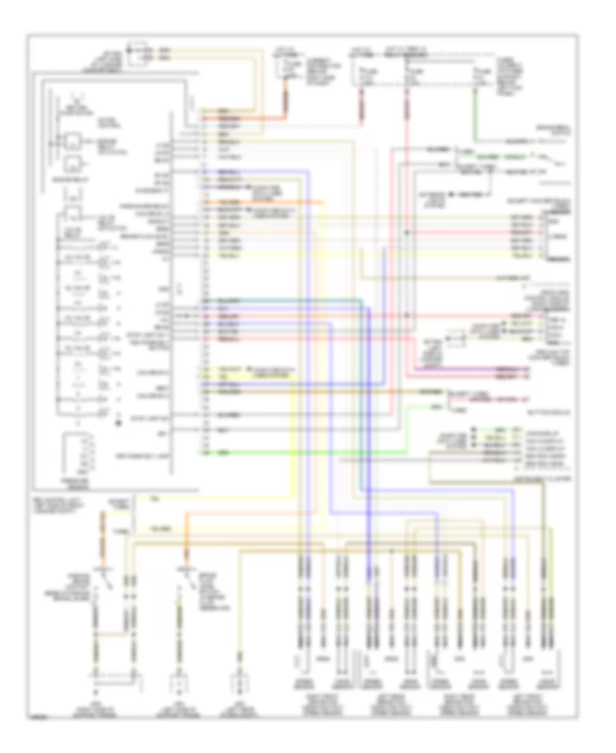
Anti-lock Brakes Wiring Diagram for Porsche 911 Targa 4 2008
List of elements for Anti-lock Brakes Wiring Diagram for Porsche 911 Targa 4 2008:
- (except convertible & turbo) ay sensor
- +cu
- Brake fluid level
- Brake fluid level switch (in brake fluid reservoir)
- Brake pedal switch
- Brk pad wear
- Brk pad wear+
- Bs +
- Button module
- Can drive hi
- Can drive lo
- Can hi display
- Can lo display
- Can-h
- Can-l
- Canwake up
- Computer data lines system
- Current distributor (behind right side of dash)
- Diagnosis "k"
- Drs can top (convertible & turbo)
- Drsr
- Drss
- Drst
- Engine relay
- Engine relay actuation
- Except turbo
- Exterior lights system
- Front end control module (right side of luggage compt)
- Fuse f10 25a
- Fuse f4 10a
- Fuse f5 50a
- Fuse f8 10a
- Fuses holder c (on fuses support, behind left kick panel)
- Gnd
- Gnd/out
- Gp psm (left side of luggage compartment)
- Gp psm (left side of luggage compt)
- Gp3 (left side of support frame)
- Gp5 (right side of support frame)
- Gp8 (left rear of eng compt)
- Hot at all times
- Inj valve
- Instrument cluster
- Left front brake pad wear contact/ speed sensor
- Left rear brake pad wear contact/ speed sensor
- Lf dp
- Lf ds
- Lr dp
- Lr ds
- Lr eos
- Motor control
- Nca
- Parking brake sw
- Pressure sensor
- Psm control unit (left side of front luggage compt)
- Psm passively button
- Psm passively lamp
- Return pump motor
- Rf dp
- Rf ds
- Right front brake pad wear contact/ speed sensor
- Right rear brake pad wear contact/ speed sensor
- Rr dp
- Rr ds
- Sensor
- Speed sensor
- Stop light sw
- Stop light sw +
- Ter 15
- Turbo
- U sens
- Valve relay
- Valve relay actuation
- Wear sensor
 English