ANTI-LOCK BRAKES
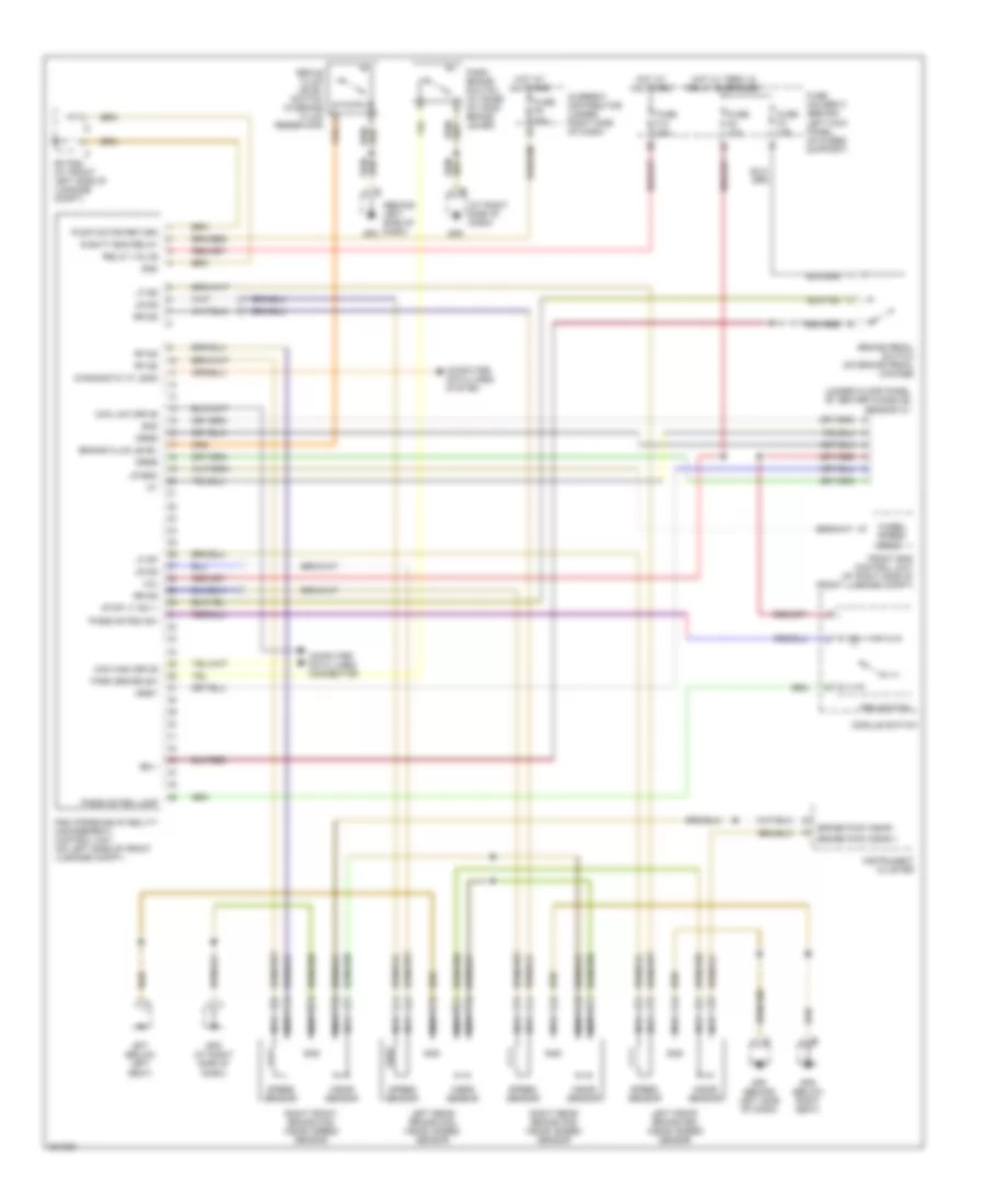
Anti-lock Brakes Wiring Diagram for Porsche Boxster S 2005
List of elements for Anti-lock Brakes Wiring Diagram for Porsche Boxster S 2005:
- (at right side of dash)
- (behind left side of dash)
- (under floor panel of center console) sensor ay
- +cu
- Brake fluid level
- Brake paid wear +
- Brake paid wear -
- Brake pedal switch (on brake pedal linkage)
- Brale fluid level switch (in brake fluid reservoir)
- Bs +
- Can high drive
- Can low drive
- Computer data lines connector
- Computer data lines system
- Current distributor (under right side of dash)
- Diagnostic "k" lead
- Drsr
- Drss
- Drst
- E batt eng relay
- Front end control unit (at right side of front luggage compt)
- Fuse f10 25a
- Fuse f4 10a
- Fuse f5 50a
- Fuse f8 10a
- Fuse holder c (behind left kick panel, on fuses support)
- Gnd
- Gp psm (at front left side of luggage compt)
- Gp3
- Gp3 (behind left side of dash)
- Gp5
- Gp5 (at right side of dash)
- Gp6 (below right seat)
- Gp7 (below left seat)
- Hot at all times
- Hot w/ term 15 relay energized
- Instrument cluster
- Left front brake pad wear/ speed sensor
- Left rear brake pad wear/ speed sensor
- Lf dp
- Lf ds
- Lr ds
- Lr eso
- Module switch
- Nca
- Park brake sw
- Park brake switch (at base of hand brake lever)
- Passive psm lamp
- Passive psm sw
- Psm (porsche stability management) control unit (on left side of front luggage compt)
- Psm switch
- Pump motor return
- Relay valve
- Rf ds
- Right front brake pad wear/ speed sensor
- Right rear brake pad wear/ speed sensor
- Rr ds
- Speed sensor
- Stop lt sw +
- Wear sensor
- Wheel speed sens
 English