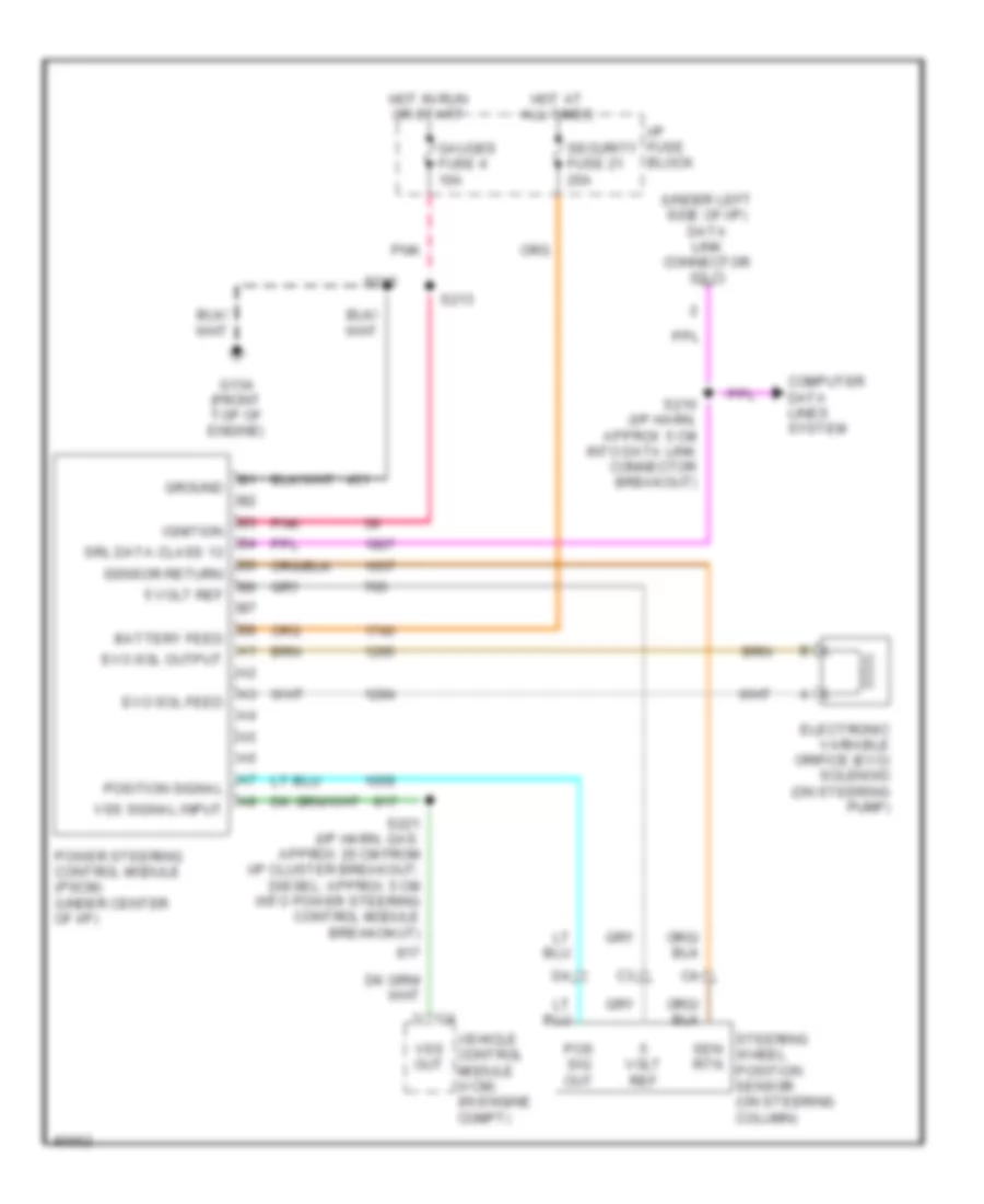
ELECTRONIC POWER STEERING
Electronic Power Steering Wiring Diagram for GMC Cab & Chassis C3500 1997
List of elements for Electronic Power Steering Wiring Diagram for GMC Cab & Chassis C3500 1997:
- (under left side of i/p) data link connector (dlc)
- 5 volt ref
- Battery feed
- Computer data lines system
- Electronic variable orifice (evo) solenoid (on steering pump)
- Evo sol feed
- Evo sol output
- G134 (front top of engine)
- Gauges fuse 4 10a
- Ground
- Hot at all times
- Hot in run or start
- I/p fuse block
- Ignition
- Pnk
- Pos sig out
- Position signal
- Power steering control module (pscm) (under center of i/p)
- S210 (i/p harn, approx 5 cm into data link connector breakout)
- S213
- S215
- S221 (i/p harn, gas: approx 20 cm from i/p cluster breakout; diesel: approx 5 cm into power steering control module breakokut)
- Security fuse 21 20a
- Sen rtn
- Sensor return
- Srl data class 13
- Steering wheel position sensor (on steering column)
- Vehicle control module (vcm) (in engine compt)
- Volt ref
- Vss out
- Vss signal input
 English