БЛОК УПРАВЛЕНИЯ КУЗОВОМ
Электросхема блока управления кузовом для Pontiac Firebird 1997
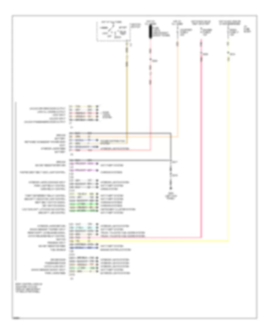
Электросхема блока управления кузовом для Pontiac Firebird 1997 - Список элементов:
- "low coolant" latching ind control
- Accy
- Anti-theft system
- Battery
- Body control module (mounted to hvac module, above right i/p insulator panel)
- Bulb test
- C10
- C11
- C12
- C13
- C14
- C15
- C16
- Courtesy fuse 8 20a
- D10
- D11
- D12
- D13
- D14
- D15
- D16
- Door locks system
- Driver door
- Engine controls system
- Exterior lights system
- Fasten seat belt indic lamp control
- Fuel enable
- Fuse link e (above right shock tower)
- G200 (left kick panel)
- Gauges fuse 9 10a
- Ground
- Hatch ajar input
- Hatch release relay control
- Horn relay control
- Horns system
- Hot at all times
- Hot in acc, run or w/ rap energized
- Hot in run, bulb test or start
- I/p fuse block
- Ign key resistor feed
- Ign key resistor return
- Ignition
- Ignition switch
- Instrument cluster system
- Interior lamps command input
- Interior lamps feed
- Interior lamps return
- Interior lights system
- Key ignition signal
- Lock
- Lock all doors output
- Lock input
- Off
- Park lamp relay control
- Park lamps feed
- Passenger door
- Pnk
- Power distribution system
- Program input
- Radio fuse 17 15a
- Rear compt lid release signal
- Red
- Retained accessory power (rap)
- Run
- S200
- S206
- S216
- S217
- S218
- Seat belt switch signal
- Security indicator lamp control
- Security led control
- Shock sensor "shock" input
- Shock sensor "tamper" input
- Start
- Tan
- Theft deterrent relay control
- Trunk, tailgate, fuel doors system
- Unlock driver's door output
- Unlock input
- Unlock passenger's door output
- Warning systems
 English