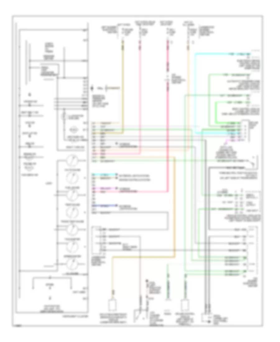
INSTRUMENT CLUSTER
Instrument Cluster Wiring Diagram for GMC Sierra 1500 1999
List of elements for Instrument Cluster Wiring Diagram for GMC Sierra 1500 1999:
- (4.3l) (others)
- (mil)
- (not used)
- (service eng soon)
- -prndl -trip -odometer -hour meter
- 4wd ind
- A10
- A11
- A12
- Abs ind
- Air bag ind
- Automatic transfer case control module (left side of dash, above headlight switch)
- B10
- B11
- B12
- Body control module (lower left side of dash, below steering column)
- Brake ind
- Check engine oil press
- Cruise control module (left rear of eng compt, on firewall)
- Cruise fuse 10a
- Cruise ind
- Data link connector (under left side of dash, below steering column)
- Electronic brake control module (left side of the inner frame)
- Engine controls system
- Engine oil pressure sensor (on left side of oil pan)
- Exterior lights system
- Fuel gauge
- G108 (left radiator support bracket)
- G117 (right rear of eng)
- High beam ind
- Hot at all times
- Hot in run
- Hot in run or start
- Hot in run, bulb test or start
- Ign 0 fuse 10a
- Ign 1 fuse 10a
- Illumination (6 bulbs)
- Ind lamp
- Inflatable restraint sensing & diagnostic module (under driver's seat)
- Instrument cluster
- Interior lights system
- Left bussed electrical center
- Left turn ind
- Logic
- Low washer switch (in washer fluid reservoir)
- Malfunction
- Message center
- Mid bussed electrical center
- Nca
- Oil gauge
- Park/neutral position switch (a/t only) (on left side of transmission)
- Pnk
- Radio
- Radio fuse 10a
- Right turn ind
- S100
- Seat belt ind
- Serial data cl ii
- Shift up ind
- Sp203 (upper left kick panel) g200
- Spare
- Speedometer
- Splice pack
- Tach output
- Tachometer
- Temp gauge
- Trans temp gauge
- Underhood bussed electrical center
- Vehicle control module or powertrain control module (left front of eng compt)
- Volts gauge
- Vss input
 English