SHIFT INTERLOCK
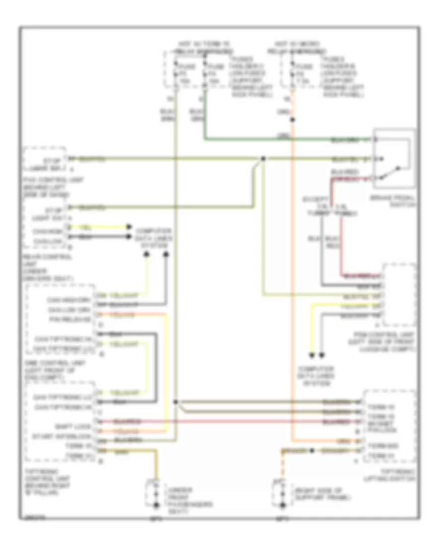
Shift Interlock Wiring Diagram for Porsche 911 GT3 2008
List of elements for Shift Interlock Wiring Diagram for Porsche 911 GT3 2008:
- (right side of support frame)
- (under front passenger's seat)
- Brake pedal switch
- Can high can low
- Can high drv
- Can low drv
- Can tiptronic hi
- Can tiptronic lo
- Computer data lines system
- Dme control unit (left front of eng compt)
- Except 3.6l 3.6l turbo
- Fuse f4 10a
- Fuse f5 15a
- Fuse f9 7.5a
- Fuses holder b (on fuses support, behind left kick panel)
- Fuses holder c (on fuses support, behind left kick panel)
- Gp5
- Gp6
- Hot w/ micro relay energized
- Hot w/ term 15 relay energized
- P/n release
- Pas control unit (behind left side of dash)
- Psm control unit (left side of front luggage compt)
- Rear control unit (under driver's seat)
- Shift lock
- Start interlock
- Stop light sw
- Stop light sw a
- Term 15
- Term 15 magnet p/n lock
- Term 31
- Term 86s
- Tiptronic control unit (behind right "b" pillar)
- Tiptronic lifting switch
- Turbo
 English