SUPPLEMENTAL RESTRAINTS
Supplemental Restraints Wiring Diagram for GMC Envoy XL 2003
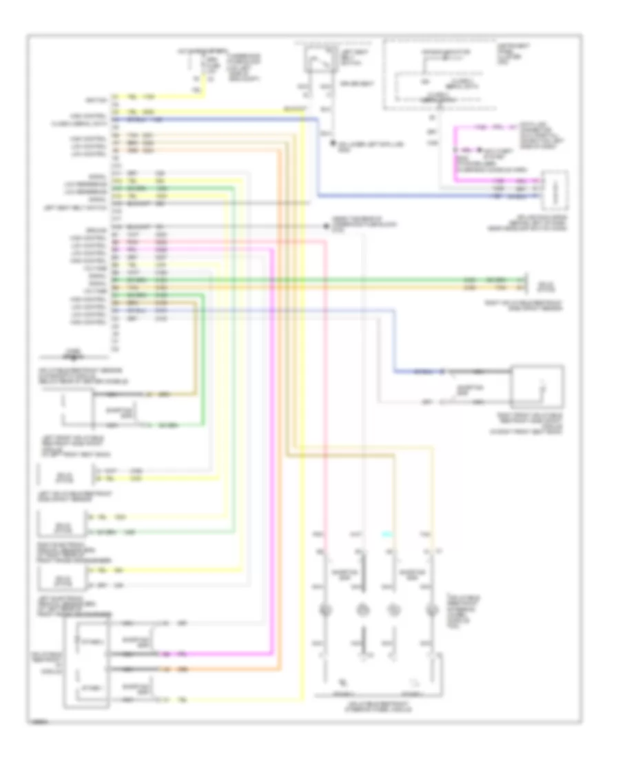
List of elements for Supplemental Restraints Wiring Diagram for GMC Envoy XL 2003:
- (near the rear of underhood fuse block) g102
- (on lower left b-pillar) g302
- A10
- A11
- A12
- A13
- A14
- A15
- A16
- A17
- A18
- Air bag indicator
- Anti-theft system
- Bar
- C1 a1
- Case ground
- Class 2 serial data
- Data link connector (dlc) (partial) (on bottom left side of dash)
- Driver seat
- Ground
- High control
- Hot in on & start
- Ign
- Ignition
- Inflatable restraint i/p module
- Inflatable restraint sensing & diagnostic module (below rear of center console)
- Inflatable restraint steering wheel module
- Inflatable restraint steering wheel module coil
- Instrument panel cluster (ipc)
- Left electronic frontal sensor (efs) (at left rear of front frame crossmenber)
- Left front inflatable restraint side impact module (in left front seat back)
- Left inflatable restraint side impact sensor
- Left seat belt switch
- Low control
- Low reference
- Nca
- Pnk
- Right electronic frontal sensor (efs) (at right rear of front frame crossmenber)
- Right front inflatable restraint side impact module (in right front seat back)
- Right inflatable restraint side impact sensor
- S232 (w/immobilizer) (overhead console harn)
- Shorting
- Shorting bar
- Signal
- Solid state
- Splice pack sp205 (behind left of dash, near headlamp switch conn)
- Srs fuse 10a
- Stage 1
- Stage 2
- Tan
- Underhood fuse block (on left side of eng compt)
- Voltage
 English