SUPPLEMENTAL RESTRAINTS
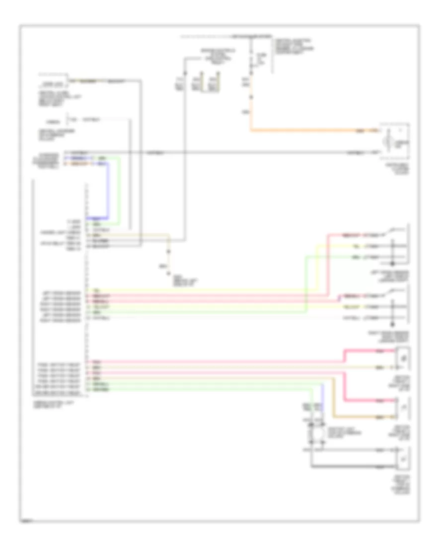
Supplemental Restraint Wiring Diagram for Porsche 911 Speedster 1994
List of elements for Supplemental Restraint Wiring Diagram for Porsche 911 Speedster 1994:
- 1/15
- 1/23
- 1/4
- 1/9
- Airbag
- Airbag control unit (center of i/p)
- Airbag ind.
- B15
- Central alarm locking control unit (below right front seat)
- Central electric (on right side member, in luggage compartment)
- Central informer (on steering column)
- Code lock
- Contact unit (top of steering column)
- Diagnosis plug socket (passenger's footwell)
- Driver ignition tablet
- E32
- E42
- Engine controls system (dme control relay)
- F12
- Fuse 7.5a
- G202 (behind left side of i/p)
- Hazard light airbag
- Hot in run or start
- Ignition tablet 1 (top of steering column)
- Ignition tablet 2 (right side of i/p)
- Ignition tablet 3 (right side of i/p)
- Instrument cluster (clock)
- K lead
- L lead
- Left crash sensor
- Left crash sensor (left side of luggage compt)
- Mfi+di relay term 86
- Nca
- Pass. ignition tablet
- Pnk
- Right crash sensor
- Right crash sensor (right side of luggage compt)
- Term 15
- Term 31
 English