AIR CONDITIONING
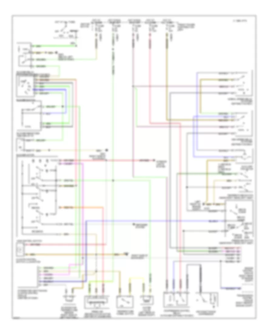
Air Conditioning Wiring Diagrams for BMW 318ti 1997
List of elements for Air Conditioning Wiring Diagrams for BMW 318ti 1997:
- (left front of engine compt)
- (right side of
- 1) above 88 deg c 2) above 80 deg c
- 1995 vftc c
- A/c
- Above 18 bar
- Above 2.6 bar
- Above 30 bar
- Acc
- Air conditioning compressor
- All times
- Auxiliary fan motor
- Below 1.5 bar
- Below 15 bar
- Below 21 bar
- Blower motor
- Blower relay (in power distribution box)
- Blower resistors (center of i/p)
- Blower switch
- Climate control switch illumination
- Compressor control relay (in power distribution box)
- Defogger system
- Engine control module (right rear of engine compt)
- Evaporator temperature sensor (right side of left footwell)
- Fresh air recirculation motor (center of dashboard)
- Front power distribution box
- Fuse 30a
- Fuse 5a
- Fuse 7.5a
- G100
- G201
- G201 (right side of glove box)
- G202 (below left side of dash)
- Glove box)
- High speed relay (in power distribution box)
- Hot at
- Hot at all times
- Hot in run
- Ignition switch
- Ihks control switch
- Integrated heating and climate control module (center of dash)
- Interior lights system
- Nca
- Normal speed relay (in power distribution box)
- Off
- Or start
- Pressure switch (near right headlight assy)
- Recirc
- Rr defog
- Run
- Solid state
- Start
- Temperature switch (near right headlight assy)
- Temperature wheel switch
- Transmission control module (right rear of engine compt)
- Water valve (left rear of engine compt)
- X10016
- X10017
- X10018
 English