AIR CONDITIONING
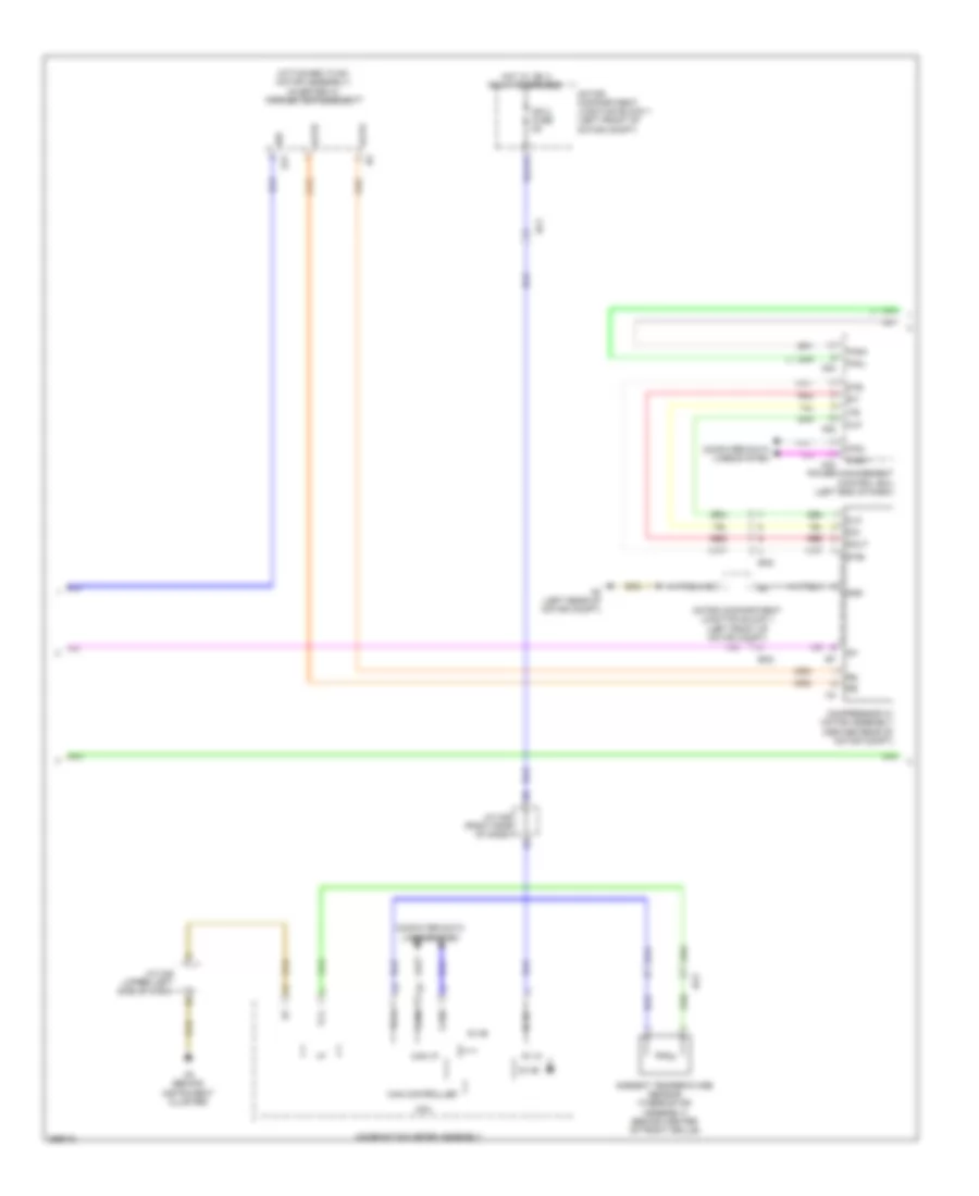
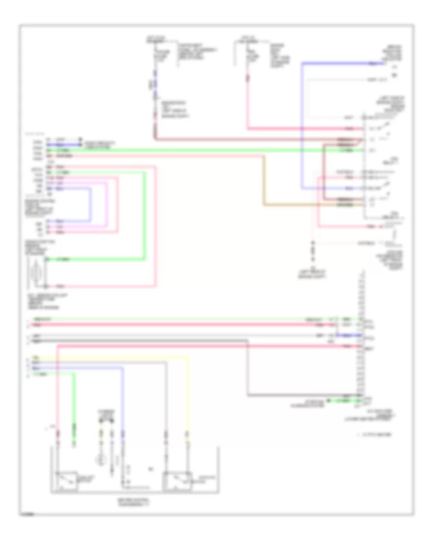
Automatic A/C Wiring Diagram, EV (1 of 3) for Scion iQ EV 2013

List of elements for Automatic A/C Wiring Diagram, EV (1 of 3) for Scion iQ EV 2013:
- (top left side of dash) automatic light control sensor
- A/c amplifier assembly (lower center of dash)
- A/c control assembly
- A/c control switch
- A/c pressure sensor (magnet valve assembly) (right side of motor compt)
- A48
- Ac2
- Ac3
- Ac5
- Acc
- Acc fuse 5a
- B13
- Blower motor w/ fan sub-assembly (center of dash)
- Blw
- C1 (behind instrument cluster)
- C25
- C4 (right kick panel)
- C45
- Canh
- Canl
- Cd1
- Cltb
- Clte
- Clts
- Computer data lines system
- Cooler (room temperature sensor) thermistor (left center of dash)
- D31
- D32
- D35
- D51
- Defogger system
- Dfac
- Discharge coolant temperature sensor (left center of dash)
- Ecu-b 7.5a
- Ecu-ig fuse 7.5a
- Exterior lights system
- Gnd
- Gnd1
- Hazard switch
- Hot at all times
- Hot w/
- Hot w/ acc relay energized
- Htr-b fuse 40a
- Htr-ig fuse 10a
- Hwd switch
- Idh
- Ig+
- Ig-1
- Ig1 1 relay energized
- Ill+
- Ill-
- Ind+
- Ind-
- Inhalation coolant temperature sensor (on accumulator assembly)
- Instrument panel j/b (behind left end of dash)
- Integration control & panel assembly
- Interior lights system
- J/c a48 & c45 (left kick panel)
- J/c c46 (upper left side of dash)
- J/c c48 (lower left side of dash)
- Lin1
- Main body ecu
- Motor compartment relay block 1 (left front of motor compt)
- Pnk
- Pre
- Rdfi
- Rdfq
- Rdsw
- Red
- S5-3
- Seg1
- Seg2
- Sg-1
- Sg-2
- Solar sensor
- Ss-
- Sw+
- Tcht
- Tclt
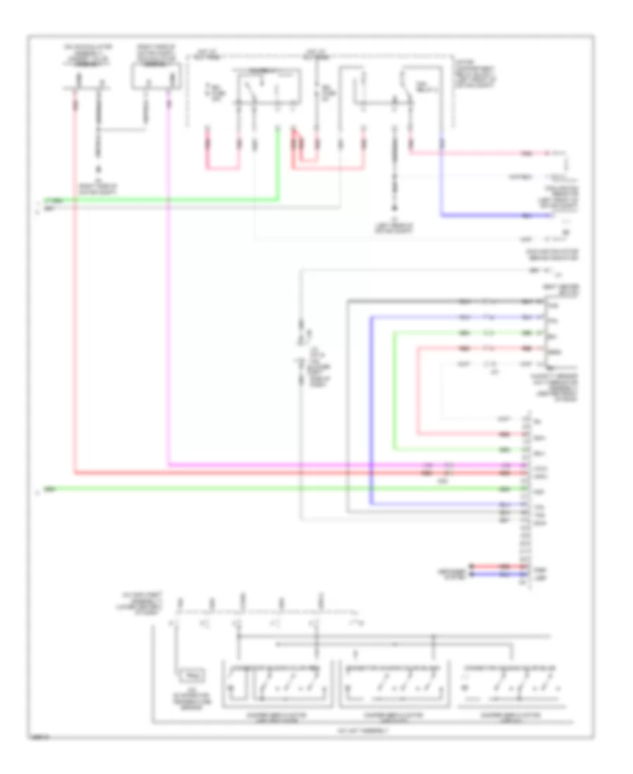
Automatic A/C Wiring Diagram, EV (2 of 3) for Scion iQ EV 2013
List of elements for Automatic A/C Wiring Diagram, EV (2 of 3) for Scion iQ EV 2013:
- (attached to ev motor assembly) inverter w/ converter assembly
- 5v ic
- 5v+b
- A2 (left rear of motor compt)
- A21
- A22
- A24
- Ac3
- Ac5
- Acpb
- Acpe
- Ambient temperature sensor (thermistor assembly) (behind center of front grille)
- Ba2
- C23
- C5 (behind instrument cluster)
- Ca2h
- Ca2l
- Can controller
- Can i/f
- Canh
- Canl
- Clk
- Combination meter assembly
- Compressor w/ motor assembly (center rear of motor compt)
- Computer data lines system
- Cpu
- Din
- Dout
- Eti
- Fanh
- Fanl
- Gnd
- Hot w/ ig2 2 relay energized
- I/f
- Idh
- Ig+
- Ig1
- Ig2 2 fuse 5a
- Ite
- J/c c46 (upper left side of dash)
- J/c c49 (right side of dash)
- Motor compartment junction block 1 (left front of motor compt)
- Power management control ecu (left end of dash)
- Red
- Stb
- Stbi
- Tx1+
- Tx1-
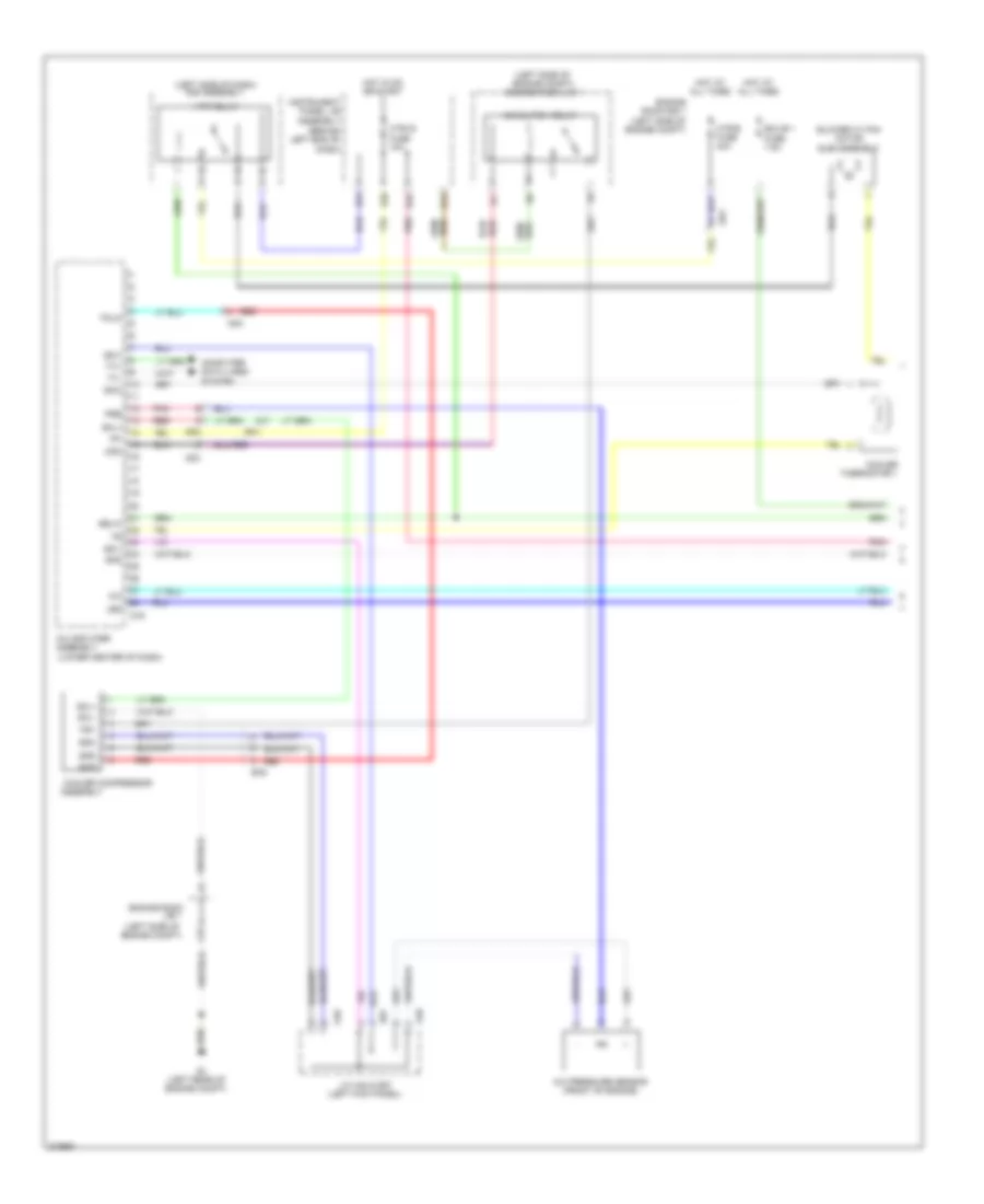
Automatic A/C Wiring Diagram, EV (3 of 3) for Scion iQ EV 2013
List of elements for Automatic A/C Wiring Diagram, EV (3 of 3) for Scion iQ EV 2013:
- (on accumulator assembly) magnet valve assembly
- (right side of motor compt) accumulator assembly
- A/c amplifier assembly (lower center of dash)
- A/c evaporator temperature sensor
- A/c unit assembly
- A1 (left rear of motor compt)
- A4 (right side of motor compt)
- Ac5
- B bus
- Bus
- Bus g
- C48
- Connector housing color (black)
- Connector housing color (red)
- Cooling fan motor (behind radiator)
- Cooling fan resistor (left front of motor compt)
- Damper servo motor (air inlet)
- Damper servo motor (air mix)
- Damper servo motor (air vent mode)
- Defogger system
- Fan relay 1
- Fan relay 2
- Fdef
- Fdfi
- Hot at all times
- Hpmv
- Htmv
- Humidity sensor (a/c thermistor assembly) (center front of roof)
- J/c c47 & c48 (lower c47
- Jc1
- Ldef
- Left side of dash)
- Motor compartment relay block 1 (left front of motor compt)
- Pnk
- Rdi fuse 30a
- Rdi fuse 5a
- Red
- S5-4
- S5v
- Seat heater switch
- Seg3
- Sg-4
- Sga
- Shin
- Tea
- Tfg
- Tng
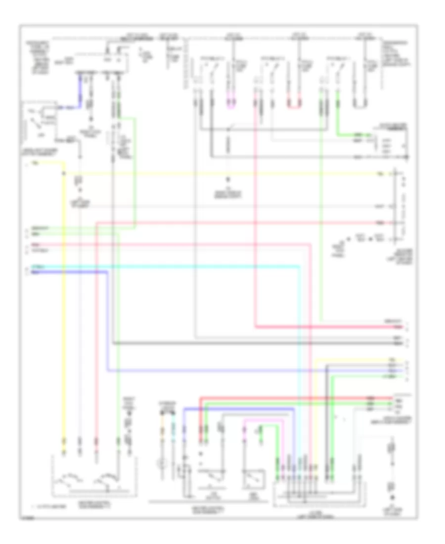
Manual A/C Wiring Diagram, Except EV (1 of 3) for Scion iQ EV 2013
List of elements for Manual A/C Wiring Diagram, Except EV (1 of 3) for Scion iQ EV 2013:
- (left side of
- (left side of dash) r/b assembly
- (left side of engine compt) engine room j/b 1
- (lower center of dash)
- A/c
- A/c amplifier assembly
- A/c pressure sensor (front of engine)
- A2 (left rear of engine compt)
- A48
- Ad2
- Ad3
- Assembly
- Assembly (behind left end of dash)
- B13
- Ba1
- Ba2
- Blower w/ fan motor sub-assembly
- Computer data lines system
- Cooler compressor
- Cooler thermistor 1
- D16
- D31
- D32
- D35
- D67
- Ecu-b 1 fuse 7.5a
- Engine compt)
- Engine room
- Engine room r/b 1 (left side of engine compt)
- Folq
- Gnd
- Hot at all times
- Hot in on or start
- Htr relay
- Htr-b fuse 40a
- Htr-ig fuse 10a
- Ig+
- Instrument panel j/b
- J/b 1
- J/c a48 & d67 (left kick panel)
- Led
- Mg clutch relay
- Mg+
- Mgc
- Pnk
- Pre
- Qufl
- Red
- S5-3
- S5fl
- Sblw
- Sg-1
- Sg-2
- Sgfl
- Sol+
- Sol-
- Tx+
- Tx-
Manual A/C Wiring Diagram, Except EV (2 of 3) for Scion iQ EV 2013
List of elements for Manual A/C Wiring Diagram, Except EV (2 of 3) for Scion iQ EV 2013:
- (behind left end
- (left d67 kick panel)
- (left side of
- (left side of dash)
- (right kick
- (right kick panel)
- (right side of engine compt)
- (w/ ptc heater)
- A48
- A48 &
- Acc
- Acc fuse 5a
- Air mix damper servo sub-assembly
- Assembly
- Auto
- B34
- B37
- Becu
- Blower resistor (left center of dash)
- D1 (left side of dash)
- D42
- D67
- Def- logic
- Ecu-ig fuse 7.5a
- Engine compt)
- Engine room r/b 2 (w/ ptc heater)
- F/r switch
- Frs
- Gnd1
- Head
- Headlight dimmer switch assembly
- Heater control sub-assembly 1
- Heater control sub-assembly 2
- Hot at all times
- Hot in on or start
- Hot w/ acc relay energized
- Hrly
- Ig+
- Instrument panel j/b
- Interior lights system
- J/c
- J/c d68 (left side of dash)
- Main body ecu
- Of dash)
- Off
- Panel)
- Pnk
- Ptc 1 fuse 50a
- Ptc 2 fuse 30a
- Ptc 3 fuse 30a
- Ptc relay 1
- Ptc relay 2
- Ptc relay 3
- Quick heater assembly
- Rec
- Red
- Tail
- Tan
- W/ ptc heater
Manual A/C Wiring Diagram, Except EV (3 of 3) for Scion iQ EV 2013
List of elements for Manual A/C Wiring Diagram, Except EV (3 of 3) for Scion iQ EV 2013:
- (behind radiator) cooling fan motor
- (left side of engine compt) engine room r/b 1
- (lower center of dash)
- A/c amplifier
- A/m & a/c
- A18
- A2 (left rear of
- Ad3
- Alt
- Assembly
- B27
- C10
- Canh
- Canl
- Charging system
- Computer data lines system
- Cooling fan resistor (left front of engine compt)
- Crank position sensor (left front of engine)
- D17
- E.f.i. engine coolant temperature sensor (rear of engine)
- Engine compt)
- Engine control module (left front of engine compt)
- Engine room j/b 1 (left side of
- Engine room r/b 1 (left side of engine compt)
- Ethw
- Fan relay 1
- Fan relay 2
- Fanh
- Fanl
- Gauge fuse 10a
- Heat
- Heater control sub-assembly 3
- Hls
- Hot at all times
- Hot in on or start
- Instrument panel j/b assembly (behind left end of dash)
- Interior lights system
- Max hot
- Ne+
- Ne-
- Pnk
- Ptc1
- Ptc2
- Ptc3
- Rdi fuse 30a
- Starting/
- Switch
- Tan
- Thw
- Vcne
- W/ ptc heater