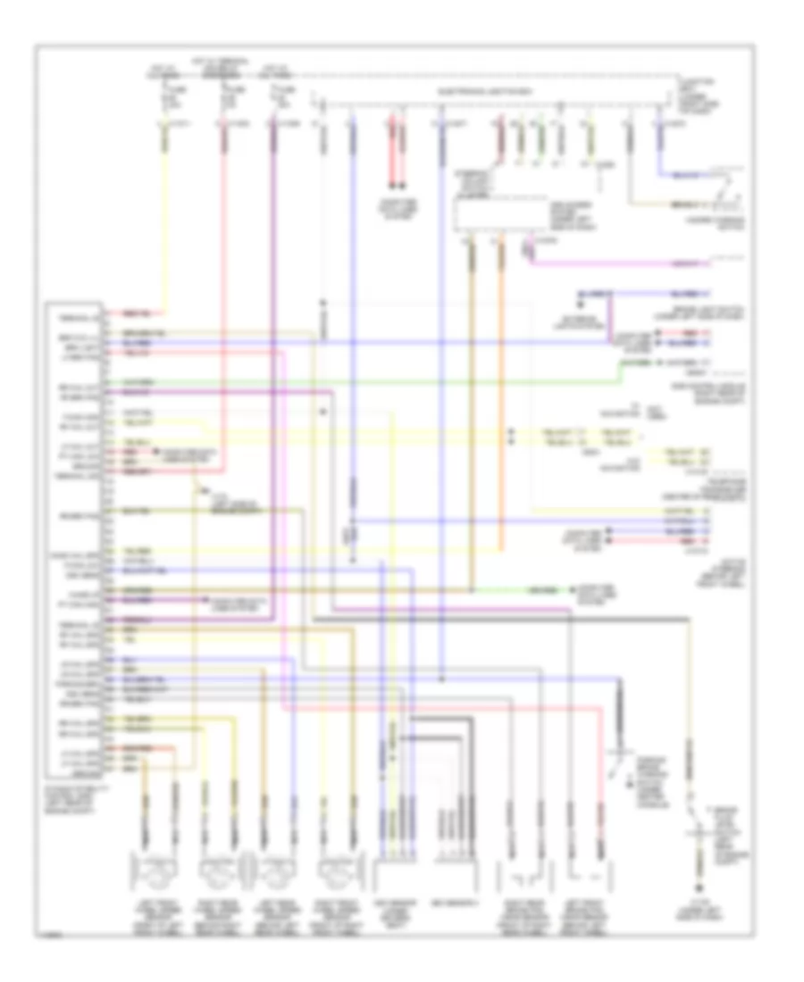
ANTI-LOCK BRAKES
Anti-lock Brakes Wiring Diagram for BMW 135i 2013
List of elements for Anti-lock Brakes Wiring Diagram for BMW 135i 2013:
- (not used)
- Active steering (behind left front wheel)
- Brake fluid level switch (left rear of engine compt)
- Brake light switch (under left side of dash)
- Brk fld lvl
- Brk light
- Car access system (under left side of dash)
- Computer data lines system
- Cond whl spd
- Dme control module (right rear of engine compt)
- Dsc sens
- Dsc sensor (under driver's seat)
- Dsc sensor 2
- Dynamic stability control (dsc) (left rear of engine compt)
- Electronics junction box
- Exterior lights system
- F-can high
- F-can-low
- Fuse 30a
- Fuse 40a
- Fuse 5a
- Ground
- Hazard warning switch
- Hot at all times
- Hot w/ terminal 30g relay energized
- Junction box (under right side of dash)
- Left front brake pad wear sensor (behind left front wheel)
- Left front wheel speed sensor (front of left front wheel)
- Left rear wheel speed sensor (behind left rear wheel)
- Lf brk pad
- Lf whl out
- Lf whl spd
- Lr whl spd
- Nca
- Parking brake warning switch (under center console)
- Parking brk
- Pt can high
- Pt can low
- Red
- Rf brk pad
- Rf whl out
- Rf whl spd
- Right front wheel speed sensor (front of right front wheel)
- Right rear brake pad wear sensor (front of right rear wheel)
- Right rear wheel speed sensor (behind right rear wheel)
- Rr brk pad
- Rr whl out
- Rr whl spd
- Steering column switch cluster
- Telephone transceiver (center of rear compt)
- Terminal 30
- Terminal 30g
- W/ navigation
- W/o navigation
- Wake up
- X1108 (under left side of dash)
- X13718
- X14133
- X170 (left side of engine compt)
- X1880
- X60001
- X9331
 English